Bridge - Ultrasonic Testing (Flaw Detection)
Target of Investigation
UT technology can be applied to truss members, steel girders, or other steel bridge components with a plate-like geometry (i.e., parallel surfaces). UT is often used for determining the thickness of a test member. Thickness gages are commonly used for the detection of section loss resulting from corrosion in steel bridge members.
UT technology can also be applied to in-service bridges to detect and/or monitor the following:
- Cracks in steel bridge members.
- Weld flaws such as cracks, slag inclusions, weld porosity, or lack of fusion in steel bridge members.
- Cracks in steel bridge components such as pins, hangers, and eyebars.
- Fractured anchor bolts.
- Thickness of a steel plate.
- Length of a bridge pin or anchor bolt.
The technology is applied during the fabrication of welded members to ensure weld quality.(1,2,3)
Description
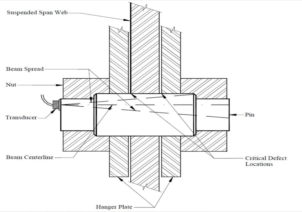
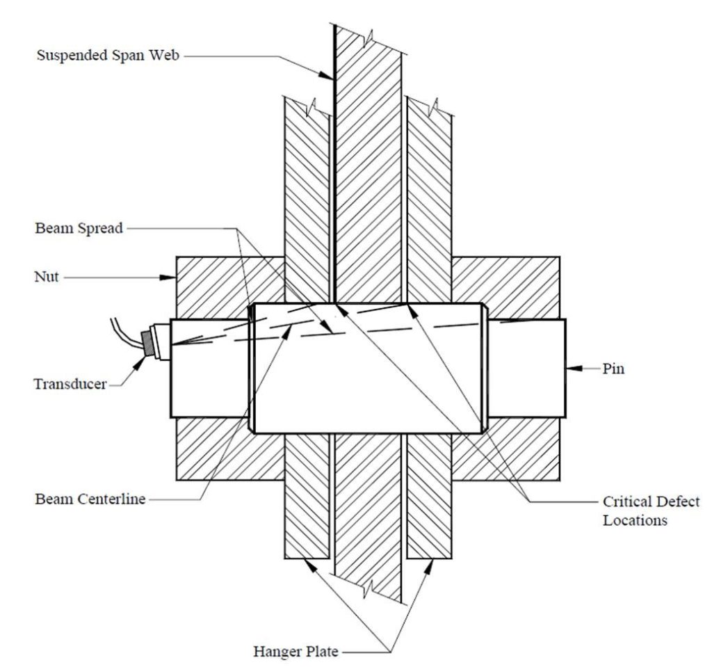
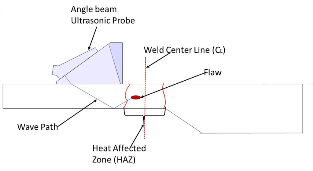
UT for flaw detection is a nondestructive method in which high-frequency acoustic waves are introduced into a material by a transducer placed on the surface. The acoustic wave propagates through the material and is reflected by discontinuities in the material. The reflected acoustic waves are detected by the transducer. The resulting waveform is analyzed to identify reflections that may be caused by discontinuities in the material. The technology can be used to detect weld flaws such as cracks, inclusions, weld porosity, or lack of fusion. The technology can also be used to detect cracks in steel members and components.(1) UT is implemented using one of two different configurations, straight-beam (figure 1) or angled-beam (figure 2 and figure 3).
Physical Principle
The physical principle of UT is that an acoustic waves (sound waves, elastic waves, or mechanical waves) passing through a material will be fully or partially reflected by discontinuities in the material or a boundary of the material. Acoustic waves are introduced into the material using an ultrasonic transducer placed on the surface. The transducer launches an acoustic wave that passes through the material and is reflected by discontinuities within the material and boundaries of the material. After the wave has passed through the material, an ultrasonic transducer is used to detect and display the resulting waveform. The waveform is analyzed to assess reflections from back wall or those caused by discontinuities in the material and the boundaries of the material.(1)
Data Acquisition
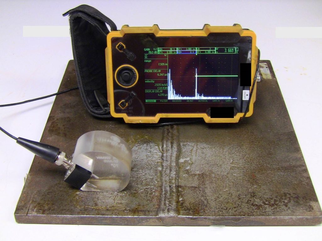
Data is acquired by using a hand-held, battery-operated ultrasonic flaw detector. The flaw detector is comprised of an ultrasonic pulser-receiver that generates and detects the acoustic waves, a screen on which waveforms are displayed, and a control panel where adjustments to instrument parameters can be made. On-board data storage is typically provided where waveforms and other test data can be saved. UT is implemented using one of two different configurations, straight-beam or angled-beam.
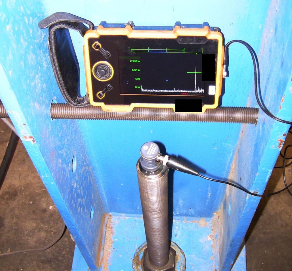
Straight-beam testing is applied in the field for detecting defects in pins, trunnion shafts, anchor bolts, and other steel bridge components. Straight-beam testing launches a longitudinal wave normal or nearly normal to the surface of the material being tested. Figure 4 illustrates the application of straight-beam ultrasonic testing for the detection of a crack in an anchor bolt. Small angles of up to 10° may be used to improve the alignment of the beam path with the alignment of a defect or to improve coverage when access to the surface of the material is limited. For example, the transducer may aligned at a slight angle relative to the axis of the bolt to focus ultrasonic energy on the barrel of the pin where cracks are likely to initiate.
Angled-beam testing is used for detecting flaws in welds (figure 5). This configuration is commonly used for fabrication inspection and may also be applied in the field. Angled-beam testing launches a shear wave into the material being tested at an angle of 33° or greater; standard angles are 45°, 60° and 70°. The angled ultrasonic beam penetrates the weld area after reflecting from the back side of the plate.
Data Processing
Data processing for flaw detection consists of amplifying the received acoustic waveforms to obtain a relative signal magnitude that allows the reflected wave amplitude to be compared to a standard. The required amplification (in dB) to match the magnitude of the reflected amplitude to the standard is measured and recorded
Data Interpretation
Data interpretation for flaw detection consists of comparing the amplitude of a detected waveform with a standard. Reflected waveforms that exceed a certain amplitude threshold relative to the side drilled hole are interpreted as flaws. Reflected waveforms that do not exceed the threshold are interpreted as noise or non-relevant indications.(2)
Advantages
- Rapid, low cost, widely available technology.
- Access to only one surface of the plate is required, providing the ability to assess areas inaccessible for visual inspection.
- Minimal training required.
- UT can detect both surface and subsurface flaws.
Limitations
- Surface preparation is required to achieve highly accurate results.
- Time consuming.
- Well trained operators required.
References
- American Society of Nondestructive Testing (ASNT) Handbook, 3rd Edition, Volume 7, Ultrasonic Testing (ET),
- 2005.AWS, Bridge Welding Code , AWS D1.5, American Welding Society, Miami, FL, 2010.
- Moore, M., Phares, B, and Washer, G.,Guidelines for Ultrasonic Inspection of Hanger Pins, FHWA, ed., USDOT, Washingon, D.C., 99, 2004


