Bridge - Ultrasonic Testing (Thickness Measurement)
Target of Investigation
UT technology can be applied to truss members, steel girders, or other steel bridge components with a plate-like geometry (i.e., parallel surfaces). UT is often used for determining the thickness of a test member. Thickness gages are commonly used for the detection of section loss resulting from corrosion in steel bridge members.
UT technology can also be applied to in-service bridges to detect and/or monitor the following:
- Cracks in steel bridge members.
- Weld flaws such as cracks, slag inclusions, weld porosity, or lack of fusion in steel bridge members.
- Cracks in steel bridge components such as pins, hangers, and eyebars.
- Fractured anchor bolts.
- Thickness of a steel plate.
- Length of a bridge pin or anchor bolt.
The technology is applied during the fabrication of welded members to ensure weld quality.(1,2,3)
Description
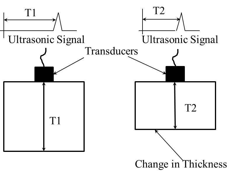
Ultrasonic thickness measurements are used to determine the section loss due to corrosion. The thickness of a material is measured based on the travel time of an ultrasonic wave that propagates through the material. A single transducer is used to launch an acoustic wave that propagates through the material to be reflected from the opposite surface and then detected by the transducer (figure 1). The time of flight (TOF) of the ultrasonic wave is determined based on the arrival time of the wave. The thickness of the material is determined from an equation (figure 2).


Where:
d = Thickness of the material (inches).
TOF = The time of flight of the acoustic wave (secs).
C = Wave velocity in the material (inches/sec).
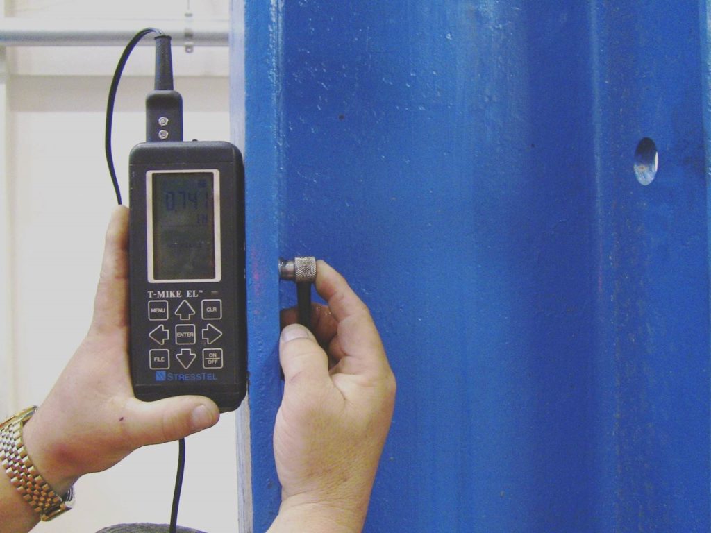
Ultrasonic thickness measurements are made with an ultrasonic thickness gauge, a hand-held, battery-operated instrument that displays the thickness measurement on a digital display.(1)
Physical Principle
The physical principle of UT is that an acoustic waves (sound waves, elastic waves, or mechanical waves) passing through a material will be fully or partially reflected by discontinuities in the material or a boundary of the material. Acoustic waves are introduced into the material using an ultrasonic transducer placed on the surface. The transducer launches an acoustic wave that passes through the material and is reflected by discontinuities within the material and boundaries of the material. After the wave has passed through the material, an ultrasonic transducer is used to detect and display the resulting waveform. The waveform is analyzed to assess reflections from back wall or those caused by discontinuities in the material and the boundaries of the material.(1)
Data Acquisition
UT thickness gage instrumentation consists of ultrasonic pulser and receiver circuitry packaged in a single hand-held, battery-operated device (figure 3). A digital display on the device indicates the measured thickness values. Some thickness gages also display data graphically to indicate thickness measurements at different locations. For example, some instruments can be attached to an encoder and graphically display the measured data along a scan line that is one-dimensional (a B-scan) or a grid that is two-dimensional (a C-scan). Measured data is stored in on-board memory and can be downloaded to a computer for reporting and further analysis.

Data Processing
Data processing for thickness measurements typically consists of a simple timing measurement to determine the time it took the acoustic wave to travel from the transducer through the material, reflect off the opposite surface, and return to the transducer. This travel time, known as the time of flight (TOF) of the acoustic wave, is then used to estimate the length of the travel path (e.g., the thickness of a plate) based on the velocity of an acoustic wave in the material. These data are shown of a digital display or graphical display, as previously described.
Data Interpretation
Most ultrasonic thickness gages provide a measurement of the travel path, requiring very little data interpretation to determine these measured values. These data are commonly interpreted for the purpose of assessing the extent of section loss due to corrosion. For example, if a steel plate with corrosion damage has an original thickness of 1 inch, and an ultrasonic thickness gage determines the actual thickness is only 0.75 inches; these data are interpreted to indicate 25 percent section loss.
Advantages
- Rapid, low cost, widely available technology.
- Access to only one surface of the plate is required, providing the ability to assess areas inaccessible for visual inspection.
- Minimal training required.
- UT can detect both surface and subsurface flaws.
Limitations
- Surface preparation is required to achieve highly accurate results.
- Time consuming.
- Well trained operators required.
References
- American Society of Nondestructive Testing (ASNT) Handbook, 3rd Edition, Volume 7, Ultrasonic Testing (ET),
- 2005.AWS, Bridge Welding Code , AWS D1.5, American Welding Society, Miami, FL, 2010.
- Moore, M., Phares, B, and Washer, G.,Guidelines for Ultrasonic Inspection of Hanger Pins, FHWA, ed., USDOT, Washingon, D.C., 99, 2004.


