Bridge - Resistance Microdrilling
Target of investigations
Resistance microdrilling is the preferred drilling and coring technique for identifying and quantifying defects, voids, and deterioration (i.e., termite galleries) in wood structures.(1)
Description
Resistance microdrilling measures the electrical power consumption of a motor as it rotates the needle.
The diameter of the needles (drill bits) at the shaft is 0.06 inch (1.5 mm) and at the tip is 0.12 inch (3.0 mm). The flat end bit (figure 1) moves through a wood member at a known rate and generates resistance information to determine the depth and extent of low-resistance areas at high precision.
Physical Principle
The electrical consumption of the resistance drill is proportional to the mechanical torque applied to the needle and mainly depends on the wood density. In other words, resistance microdrilling detects the low-density regions of wood potentially caused by decay and deterioration.(1)
Data Acquisition
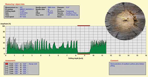
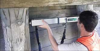
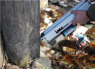
Resistance microdrills collect and store data electronically, and they can provide a chart or a hard copy representing the relative resistance of wood over the drilling path.(1) Recent models have capabilities to visualize data on a tablet or cell phone during field testing. The data can be further analyzed in the office. Depending on the density of the wood species, sound regions of wood show different levels of resistance. In contrast, voids show zero resistance against drilling (figure 2). Through observing the variation of resistance during drilling, an inspector can identify and quantify the extent of decay as low, moderate, or severe in wood members. After drilling, the drilling hole is typically filled with a small amount of silicone sealant or marine adhesive.(1) While resistance microdrilling is typically performed perpendicular to wood members, it is also possible to drill a member at an angle to assess the condition of wood below the ground line, shown in figure 3.

Figure 1. End of resistance microdrill needles (bits) [1].

Figure 2. Data. Resistance microdrill data for a southern yellow pine piling with decay region between 8–10 inches on the drilling path (yellow arrow). The decayed area shows substantially lower resistance against drilling.(1)

A. Resistance microdrilling perpendicular to the member surface.

B. Resistance microdrilling at an angle.
Figure 3. Photos. Perpendicular and angled Resistance microdrilling.(1)
Data Processing
Drilling charts should be reviewed by the inspector in the field, and notes should be taken on the charts to identify the location of drilling The instrument is often equipped with a laptop and software for a better observation of the data (figure 2).
Data Interpretation
Care must be taken not to interpret the sound of softwood (i.e., conifers) as decayed wood. The center section of the softwood (close to the pitch) is often softer than its outer section because it lacks the growth rings present in the outer region. (1) The type of wood being drilled matters. While the resistance of hardwood can be greater than 50 percent, the resistance of softwood can vary in the range of 15–50-plus percent. Drilling should be performed across the whole cross section of the member because some wood species may show constantly low resistance during the test.
The drilling resistance from different manufacturers can be substantially different due to factors such as different scales applied to the data. A guideline for determining various decay levels is presented in table 1.(1)
Table 1. Guideline for estimating the decay level of Douglas-fir and southern yellow pine using the resistance microdrill data [1].
| Resistance level (%) * | Decay level | Comments |
|---|---|---|
| > 20+ | None to low | Sound wood often shows consistent resistance across the full width |
| 5-15 | Moderate | It often represents areas near void |
| 0 | Severe | Typically represents voids |
*Values can substantially vary between manufacturers.
Advantages
Advantages of resistance microdrilling include the following:
- Resistance microdrilling provides quantitative data about the condition of wood members.
- Resistance microdrilling is simple.
- Resistance microdrilling provides an accurate depth of decay.
- Resistance microdrilling is well developed.
- Resistance microdrilling does not require access to the opposing side of wood members.
Limitations
Some of the limitations of resistance microdrilling include the following:
- This technique involves localized measurements.
- The test is mainly used to confirm the presence of decay but can also be used to determine depth of checks.
- The accessibility to the member of interest can be limited. There must be enough space for fitting the drill and drilling through the entire thickness of a member.(2) Typically, this is not an issue with bridges, where an inspector can drill vertically from the bottom side upward, even in the case of closely paced bridge girders.
- The weight of the device can cause fatigue for the inspector after several drillings.(2)
- The intended drill path can deflect from a straight line when the drill bit is boring tangentially to the growth rings.
References
- White, R. H., and R. J. Ross, eds. 2014. Wood and Timber Condition Assessment Manual. 2nd ed. General Technical Report No. FPL-GTR-234. Madison, WI: U.S. Department of Agriculture, Forest Service, Forest Products Laboratory.
- Riggio, M., R. W. Anthony, F. Augelli, B. Kasal, T. Lechner, W. Muller, and T. Tannert. 2014. “In Situ Assessment of Structural Timber Using Non-destructive Techniques.” Materials and Structures 47, no. 5: 749–766.


