


Pavements - Magnetic Pulse Induction (MPI)
Target of Investigation
Magnetic pulse induction has the following two primary applications for use in pavements:
- Determination of the thickness of concrete and asphalt pavements.
- Evaluation of dowel placement in unreinforced-concrete pavement.
Description
Magnetic pulse induction applications are based on magnetic pulse induction, but they do not use the same equipment.
Pavement Thickness
Sufficient slab thickness is critical to the long-term performance of concrete and asphalt pavements because even a small deficit in thickness can significantly reduce a pavement’s service life. The current, typical method for determining pavement thickness is to take core samples, which is destructive and costly. Using Magnetic Pulse Induction is less expensive, faster, and nondestructive; it can also be done more frequently and on a larger scale, resulting in a more robust statistical analysis.(2) Since metallic reference plates need to be placed on the base before paving, this method is limited to quality control and acceptance testing during construction of new pavements or life-cycle evaluation in pavements in which the disks were installed during construction.(1) Magnetic Pulse Induction can be used as soon as the pavement is solid enough for foot traffic.(2) This method can be used on both asphalt and concrete pavements, but it cannot be used if steel reinforcement is present.(1)
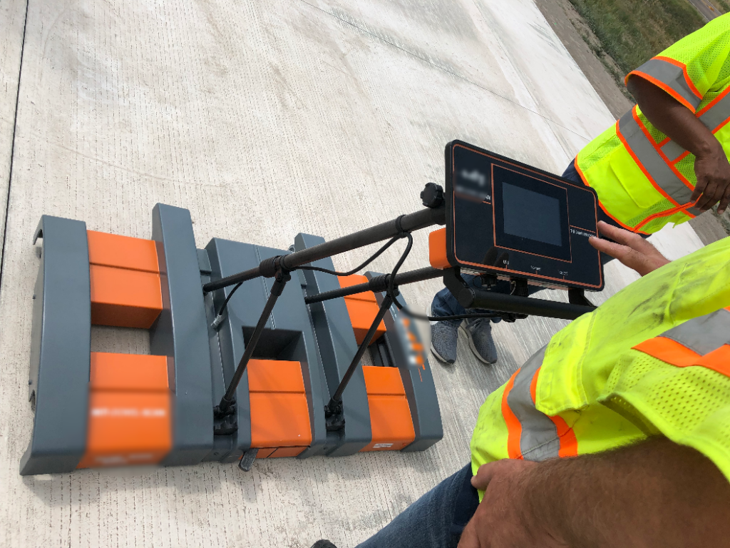
The typical Magnetic Pulse Induction system used to accurately measure the thickness of both asphalt and concrete pavements is simple, widely used, nondestructive, and cost efficient.(3) The system consists of a handheld device with a magnetic induction coil, sensors mounted in a rolling base, reference plates and a built-in processing computer (figure 1).. The method eliminates biases caused by variations in the properties of concrete and asphalt materials and can measure thicknesses up to 20 inches (508 mm).(1) The system cannot be used accurately in the presence of other metal objects. The reference plates vary based on the material of the pavement; aluminum plates and foils are used with asphalt, and galvanized steel plates are used with concrete.(4) The system’s manufacturer supplies precalibrated plates.
 Source: FHWA.
Dowel Placement
Using properly sized and positioned dowels is important for jointed concrete pavements subjected to heavy truck loads to prevent the development of roughness caused by faulting. Misaligned dowels can cause joints to lock, leading to spalling and cracking, and severe misalignments can cause looseness around the dowels under the joint, greatly reducing their effectiveness. Improper centering of the dowels under the joint can also severely impact the proper embedment length required on either side of the joint.(5) Magnetic Pulse Induction can be used to evaluate newly constructed or existing concrete pavements and to monitor and adjust the pavement process during construction.(6) The presence of other metal objects, such as tie bars, nails in the joint, coins, and pieces of wire, in the vicinity of the joint being tested severely limits the method.(6)
The typical Magnetic Pulse Induction system used to determine the position and orientation of dowels embedded in concrete pavements is simple, purpose built, nondestructive, and efficient.(5) The system consists of a sensor unit and an onboard computer(figure 2).(6) The system is based on the principle of magnetic imaging tomography. The system is rolled along the joint on tracks placed for data collection and requires less than 1 min to scan one joint. The field data analysis is fully automated and performed by the onboard computer.(6) The data analysis algorithms determine the position of the metal dowels in the pavement.(5)
 Source: FHWA.
Physical Principle
Systems for pavement thickness measurement and dowel placement are based on Magnetic Pulse Induction, by which the responses of the investigated objects to external fields are measured in space and time. These signals contain information on the distribution of electrical conductivity and magnetic properties of the investigated objects, allowing for determination of their position, size, shape, and orientation.(6)
Pavement Thickness
The typical Magnetic Pulse Induction system for measuring pavement thickness uses a pulsed induction method based on electromagnetic eddy current technology, which has high noise immunity. The measurement sensor contains a transmission coil that generates a time-dependent magnetic field (emission field) that penetrates the pavement layer. A reference plate is preplaced at the bottom of this layer. The pulsating magnetic field induces eddy currents in the reflector that subside exponentially and generate a time-dependent magnetic field. Several sensors in the measuring probe assess the response field in its time course. Alternately switching the current on and off in very short intervals generates the emission field. To avoid an overlap between the response and emission fields, the response field is measured once the emission field has completely subsided. Measurement data are collected by a defined pass over the reflector, during which each of the four receiving sensors collects up to 150 position-dependent measurement points. The signals received depend on the relative position of the instrument to the reflector and the reflector’s shape, size, and material. The relationships between these parameters and the measured signal are precisely determined during the manufacturer’s calibration.(3) AASHTO and ASTM provided standard methods of tests for pavement thickness by magnetic pulse induction.(8,9)
Dowel Placement
The typical Magnetic Pulse Induction system for determining the position and orientation of dowels uses pulse induction. The device emits a weak, pulsating magnetic signal and detects the transient magnetic response signal induced in the dowels. The weak magnetic field emitted by the system is harmless to the surrounding area and does not affect the physical properties of the dowels or the concrete. The response signals are measured with high precision using special receivers in the device, and the detected signals’ values are recorded at a relatively high sampling rate to assure large quantities of data for mathematical evaluation. This enables evaluation of measurements taken under less-than-ideal circumstances, such as in the presence of foreign metal or magnetic aggregates.(6) ASTM E3013 covers the equipment, field procedures, and interpretation methods for the assessment of dowel alignment in concrete pavements using Magnetic Pulse Induction.(7)
Data Acquisition
Pavement Thickness
Operation of the system consists of the following two phases:(1)
- Prior to concrete placement—reference plates are placed at desired locations on the surface of the base (figure 3). The reflectors need to be fastened to the base. Common powder actuated guns are commonly used to fasten them down. Reference plates should be placed away from dowels and tie bars.
 Source: FHWA.
- Following concrete placement—Testing can be conducted as soon as the concrete is solid enough for foot traffic. This phase involves the following three steps:
- Assemble the device.
- Locate the reflector using both the approximate marked location and a more accurate locator built into the system.
- Scan over the reflector. Once the location of the reflector is determined, the system is moved over the reflector at a steady speed (figure 1). Immediately after the scan is complete, a calculated thickness is displayed and recorded. Ideally, five measurements should be taken at each reference plate and the average value used.
 Source: FHWA.
Dowel Placement
Operation of the system consists of the following steps:(6)
- Ensure the system is ready before deployment. This preparation includes charging the system and ensuring enough flash storage is available for new data.

Figure 5. Photo. Magnetic pulse induction system scanning a joint to determine dowel placement.(6)
- Pull the system along the joint to collect data. Data are automatically collected and processed (figure 4).
Data Processing
Acquired data can be used to produce reports for both Magnetic Pulse Induction applications.
Pavement Thickness
No data processing is required beyond averaging multiple measurements at a single test location. The measurements are delivered in real time and can be printed in a basic report using a pocket printer.(3)
Dowel Placement
No data processing is required for ideal circumstances, because the analysis appears on the screen and can be printed.(5) For other conditions, such as the presence of foreign metal or magnetic aggregates, accompanying computer software can be used to conduct more comprehensive analyses. Software give the user greater control over the analysis process.(6)
Data Interpretation
Users require related experiences and knowledge to interpret processed data.
Pavement Thickness
The measured values of the pavement thickness by the Magnetic Pulse Induction system are accurate to within 0.1 inches (2.54 mm) according to U.S. field trials and have acceptable accuracy and repeatability for quality assurance testing.
Dowel Placement
The results are accurate if no foreign metal objects are within 3 ft (0.9 m) of the dowels being scanned.
The graphical output of the system consists of a contour map displaying the signal strength for each dowel and a diagram showing the side views of each dowel’s actual position relative to its specified location (figure 5).(5)

Figure 6. Screen capture. Graphical output display of magnetic pulse induction system for determining dowel placement.(5)
Advantages
Magnetic Pulse Induction has provided advantages to pavement thickness and dowel placement applications.
Pavement Thickness
Advantages of using Magnetic Pulse Induction to determine pavement thickness include the following:
- Provides accurate results.
- Delivers nondestructive, faster, and less expensive results than coring.
- Displays measurements in real time.
- Requires no data processing.
- The measurement is independent of the paving materials.
Dowel Placement
Advantages of using Magnetic Pulse Induction to determine dowel placement include the following:
- Provides accurate results.
- Delivers real-time display and analysis.
- Requires little or no data processing.
Limitations
There are limitations to Magnetic Pulse Induction applications.
Pavement Thickness
Limitations of using Magnetic Pulse Induction to determine pavement thickness include the following:
- Requires use of reference plates installed on base prior to paving.
- Cannot be used with reinforced pavements.
- Provides different measurements over the reference plate (smooth bottom) than a normal core measurement (uneven bottom).
Dowel Placement
A limitation of using Magnetic Pulse Induction to determine dowel placement is the following:
- Not accurate when metal objects are within 3 ft (0.9 m) of dowels being tested.
- Not accurate if shipping wires are not cut for dowel baskets.
References
- Ye, D. and Tayabji, S. (2009). TechBrief: Determination of Concrete Pavement Thickness Using the Magnetic Imaging pulse induction Technique, Report No. FHWA-HIF-09-023, Federal Highway Administration, Washington, DC.
- Federal Highway Administration. (2015). “The MIT-Scan-T2 (T2).” (website) Washington, DC. Available online: http://www.fhwa.dot.gov/pavement/concrete/scant2.cfm, last accessed April 25, 2016.
- MIT Mess- une Prüftechnik GmbH. (2013). Thickness Measuring Device – MIT-SCAN-T2: Description of the Method, MIT Mess- une Prüftechnik GmbH, Dresden, Germany. Available online: http://www.mit‑-dresden.de/fileadmin/daten/Downloads/
Description_of_the_Measuring_Method.pdf, last accessed April 25, 2016. - MIT Mess- une Prüftechnik GmbH. (2016). MIT-SCAN-T3, Product Brochure, MIT Mess- une Prüftechnik GmbH, Dresden, Germany. Available online: https://www.mit-dresden.de/fileadmin/daten/Downloads/Schichtdickenmessung/Folder_MIT-SCAN-T3_ENG_DINA4WEB112017.pdf, last accessed October 7, 2019.
- Yu, H.T. (2005). TechBrief: Use of Magnetic pulse induction Technology to Evaluate Dowel Bar Placement, Report No. FHWA-IF-06-002, Federal Highway Administration, Washington, DC, Available online: https://www.fhwa.dot.gov/pavement/pccp/pubs/06002/06002.pdf, last accessed October 7, 2019.
- Yu, H.T. and Khazanovich, L. (2005). Use of Magnetic pulse induction Technology to Evaluate Dowel Placement, Report No. FHWA-IF-06-006, Federal Highway Administration, Washington, DC. Available online: https://www.fhwa.dot.gov/pavement/concrete/mitreport/mitscan.pdf, last accessed October 7, 2019.
- ASTM E3013/E3013M-17 (2017). “Standard Test Method for Evaluating Concrete Pavement Dowel Bar Alignment Using Magnetic Pulse Induction.” Book of Standards 04.03, ASTM International, West Conshohocken, PA.
- AASHTO T 359M/T 359, 2018 Edition, 2018 – Standard Method of Test for Pavement Thickness by Magnetic Pulse Induction
- ASTM E3209 / E3209M-20, Standard Test Method for Pavement Thickness by Magnetic Pulse Induction, ASTM International, West Conshohocken, PA, 2020, www.astm.org
- NDT Thickness Measurements for Concrete Pavements – It really works! Jim Grove, Kevin Jones, Dan Ye, and Jagan Gudimettla TRB Paper 12-2081