Bridge - Magnetic Particle Testing (MT)
Target of Investigation
MT is commonly applied for crack detection in steel girders, steel truss members, and ancillary steel structures such as sign supports and light poles. The method may be applied during the fabrication process to ensure the quality of welds or may be applied to in-service structures for the detection of cracks developed from service loads.
Description
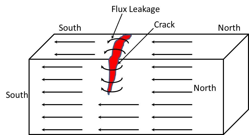
MT is a method of locating surface and subsurface discontinuities in ferromagnetic materials. When the material or part being tested is magnetized, magnetic discontinuities that lie in a direction transverse to the direction of the magnetic field, a leakage field is formed at and above the surface of the part. The presence of this leakage field, and therefore the presence of the discontinuity, is detected by using finely divided ferromagnetic particles applied over the surface, with some of the particles being gathered and held by the leakage field. This magnetically held collection of particles forms an outline of the discontinuity and indicates its location, size, shape, and extent. Magnetic particles are applied over a surface as dry particles or as wet particles in a liquid carrier such as water or oil.
Physical Principle
MT works on the physical principles of magnetic induction and magnetic field leakage. This method can only be applied to ferromagnetic materials, such as steel. When a specimen is subjected to a magnetic field, the presence of a defect will cause local distortions in the magnetic field around the defect area. This effect is referred to as magnetic flux leakage. If fine particles of magnetic material are placed on the specimen in the presence of the magnet field, they will become oriented in alignment with the magnetic flux lines and the disruption of those lines caused by a defect.

Data Acquisition
MT is typically applied using a “dry powder” method for crack detection in steel bridge components. Magnetic particles infused with a colored dye are broadcast onto the surface of the material under test. A blower may be used to remove excess powder from the surface; particles not confined by a magnetic field are removed, particles confined by magnetic forces remain forming the indication.
Surface preparation for applying MT includes removing coatings to ensure effective coupling of the magnetic field into the material under test. Removing the coating also reduces the likelihood of nonrelevant indications forming from debris on the surface or imperfections in the coating itself. Debris or imperfections in the coating can mechanically confine the particles resulting in a nonrelevant indication. Care must be taken to ensure crack openings are not obscured during coating removal using mechanical removal processes (e.g., grinding).
The orientation of the magnetic fields induced in the material must be orthogonal to a crack opening to ensure sufficient leakage field to capture magnetic particles. Direct magnetization using prods develops circular magnetic fields around each prod. Consequently, the orientation of a crack must lie parallel to an imaginary line connecting the prods. In contrast, indirect magnetization results in a magnetic field in the material that is parallel to an imaginary line connecting the yokes. Therefore, the crack must be oriented orthogonal to an imaginary line connecting the yokes. When the orientation of cracks is not known, procedures for MT typically require reorientation of the yokes or prods in orthogonal positions to ensure cracks are detected reliably.(1)
Data Processing
Crack indications are detected by visual inspection; therefore, no processing of data is required.
Data Interpretation
The primary data acquired from MT are indications on the surface of the material created from accumulated magnetic particles. These indications are interpreted by an inspector to determine if the source of the indication is a crack or if the indication is caused by a non-crack geometric feature, contamination on the surface of the material, or some other nonrelevant source. Relevant indications (i.e., crack indications) are documented by the inspector through notes, photographs, and/or diagrams.
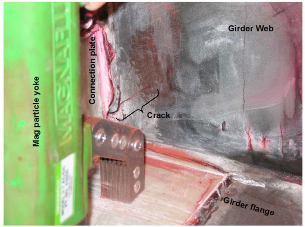
Figure 2 shows typical MT crack indications in a weld that connects a vertical stiffener to a girder web.

Advantages
- Low cost.
- Widely available on a commercial basis.
- Minimal data processing.
- Simple interpretation of results.
Limitations
- Detects only surface-breaking or very near surface flaws.
- Surface preparation required.
References
- ASTM, Standard Guide for Magnetic Particle Testing, E709-08, ASTM International, Conshohcken, PA, 2008.


