Bridge - Magnetic Flux Leakage (MFL)
Target of Investigation
The MFL method can be used to detect the location and extent of corrosion in post-tensioned and precast prestressed strands in concrete girders, and breakage of wires and strands in post-tensioning tendons and prestressing strands. MFL is also commonly used to test the cables of suspension or cable stayed bridges. MFL units can be clamped onto a cable as part of a climbing module or rolled across a surface.
Description
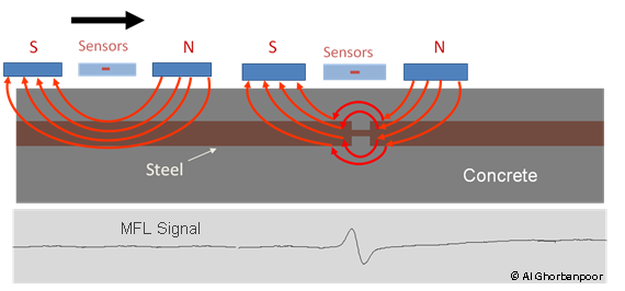
The MFL method uses a magnetic field to detect flaws in ferromagnetic materials such as steel in bridge components like prestressed girders, post-tensioned girders and decks, and suspension cables. The technique involves using an electromagnet or a permanent magnet yoke to magnetize the object being tested. The injected magnetic fluxes flow through the ferromagnetic object because it has a higher permeability than air. Any defect or discontinuity in the test object causes leakage of magnetic fluxes from the object, detectable by magnetic field sensors. It is very similar to magnetic particle testing, however instead of using magnetic particles to create a visual indication on the surface, MFL uses sensors and data processing to provide real-time results during inspections.
Physical Principle
MFL equipment magnetizes embedded reinforcement bar (like steel, prestressed element/strand, post-tensioned tendon, etc.) inside a concrete structure along its length via an external magnet. The potential leakage of the magnetic field from the magnetized reinforcement is evaluated by one or more magnetic sensors within the MFL equipment.(1) The output of the sensors is normally recorded in the form of the magnetic signal amplitude as a function of the position along the length of the reinforcement being tested (figure 1). Without flaws present, the internal magnetic flux lines are uniform and travel through the material. Any change in the magnetic field within reinforcement can be linked to the extent of section loss from corrosion or fracture in the reinforcement.

Data Acquisition
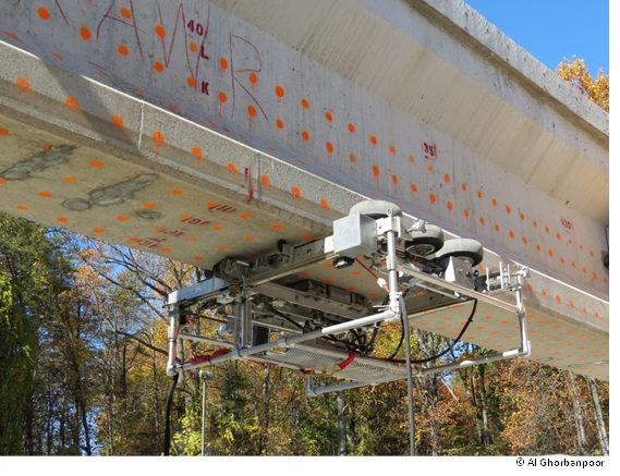
Only a limited number of private service entities possess the required equipment to perform MFL tests on concrete girders or decks. One or more magnetic sensors are used in the MFL equipment. MFL equipment may be operated manually by moving the equipment on the top of a bridge deck or close to the concrete surface and along the length of the prestressing strands or post-tensioning tendon located inside the concrete. It is also possible to use a robotic mechanism to perform the MFL testing with little to no interruption of traffic flowing under bridge girders (figure 1). For MFL testing on the underside of prestressed adjacent box girders, platforms are necessary for operating the equipment.(1)

Data Processing
Postprocessing of the MFL data is required when detecting small section losses, e.g., less than approximately 10 percent or when there are interfering materials and elements near the prestressing strands or post-tensioning tendons inside concrete. Such postprocessing approaches include comparative and correlation analyses based on existing results from known laboratory and field conditions.
Data Interpretation
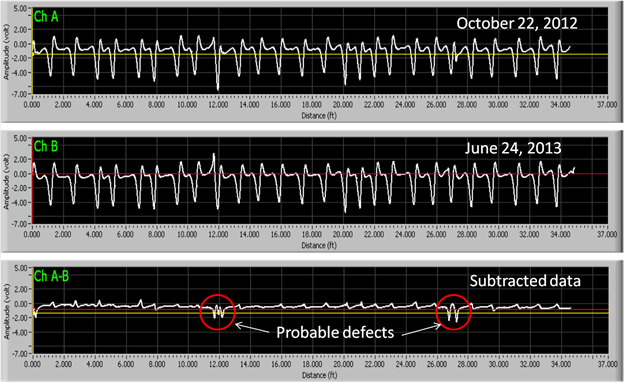
The operator monitors the magnetic field amplitude as a function of the test position on a computer screen in real time to identify changes in the magnetic field. In the absence of interfering ferromagnetic materials in the surrounding areas of prestressing strands or post-tensioning tendons, a real-time visual examination of the MFL data or graphs can offer sufficient knowledge about the lack or presence of corrosion or fracture in the strands. Any changes in the magnetic field can be directly related to section loss in the prestressing strands or in the post-tensioning tendons due to corrosion or fracture.(2) When there are interfering ferromagnetic materials near the prestressing strands or post-tensioning tendons, more advanced analysis and interpretation of the MFL signal are necessary. Figure 2 shows a MFL graph for a prestressing strand in an in-service bridge that includes a strand fracture as well as transverse steel bars (stirrups).

Advantages
- Ability to make a qualitative estimate of section loss.
- Rapid testing of a large number of surface areas.
- Automated testing of concrete girders allows for testing with little to no interruption to traffic.
Limitations
- Difficult data interpretation when interfering ferromagnetic materials are present.
- Only reliable for post-tensioning tendons and prestressing strands within approximately 6 inches of the concrete surface.
- Inexact measurements of flaw sizes (section losses).
- Uses specialized equipment not readily available commercially.
- Requires well-trained and experienced operators.
References
- Ghorbanpoor, A., Borchelt, R., Edwards, M., and Abdel Salam, E., Magnetic-Based NDE of Prestressed and Post-Tensioned Concrete Members – The MFL System, FHWA-RD-00-026, Federal Highway Administration, US DOT, May 2000.
- McGogney, C., “Magnetic Flux Leakage for Bridge Inspection,” Nondestructive Testing Methods for Civil Infrastructure, pp. 31-44, 1995.


