Bridge - Half-Cell Potential (HCP)
Target of Investigation
The half-cell potential (HCP) method can be used to identify corrosion activity of steel reinforcement in reinforced concrete structures. However, the method cannot directly measure the degree of corrosion.
Description
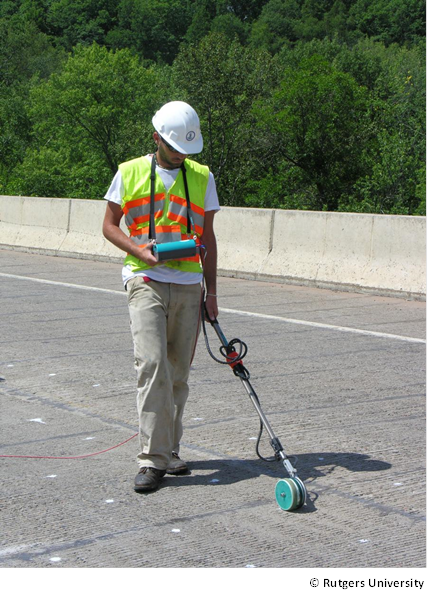
HCP measurement is based on the coexistence of corroding areas (or anodic half-cells) and non-corroding areas (or cathodic half-cells) on rebar. The measurement is calculated as the potential differences, or voltages, across the steel-concrete interfaces. The potential difference between a standard portable half-cell, typically a Cu/CuSO4 electrode, and the reinforcing steel of a concrete element is measured.(1) When the reference electrode is moved along a line or grid on the surface of a member (figure 1), the spatial distribution of corrosion potential can be mapped. Any change in the potential between the reference electrode and the steel-concrete interface can be attributed to, among other things, the corrosion activity at the surface of the steel.
The HCP measurement is a well-established and widely used electrochemical technique to evaluate active corrosion in steel reinforced and pre-stressed concrete structures.(3) HCP measurements should be taken on a clean concrete surface since presence of isolating layers (asphalt, coating, and paint) may make measurements erroneous or impossible. Using empirical comparisons, the HCP’s results can be linked to the probability of active corrosion.
Physical Principle
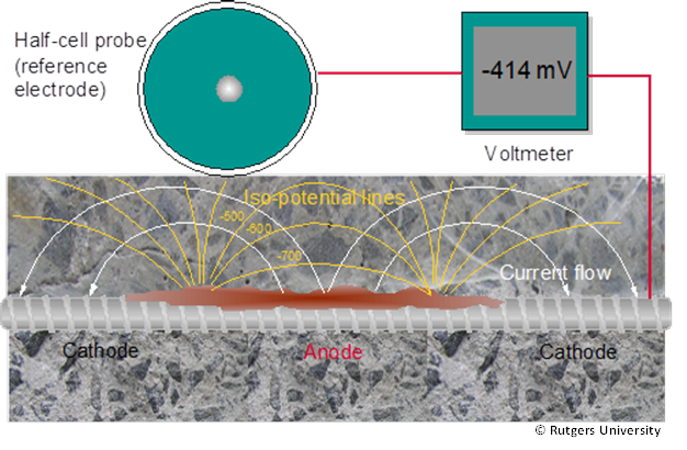
Figure 2 depicts the principle of the HCP method. Corrosion of steel in concrete is similar to the electrochemical mechanism of corrosion of a metal in an electrolyte. This implies that separate anodic and cathodic processes take place simultaneously on the same metal surface. At the corroding side (the anode), iron is dissolved and oxidized to iron ions, leaving electrons in the steel. At the cathodic side of the reaction, oxygen is reduced and hydroxyl ions are produced. The potential of the generated electrical field is measured by a reference electrode. The reference electrode is connected to the positive end of a voltmeter and steel reinforcement to the negative one. The reference electrode is usually galvanically coupled to the concrete surface using a wet sponge. The input impedance of the voltmeter should be in the range of 106Ω to 109Ω.
Data Acquisition
ASTM C876–09, Standard Test Method for Half-Cell Potentials of Uncoated Reinforcing Steel in Concrete, describes the HCP test method. The test procedure on a bridge deck can be summarized in the following steps:(4)
- Lay out a 2ft by 2ft grid on the deck.
- Locate the top reinforcing bar using a rebar locator (GPR or pachometer) at several points along the bridge deck. A minimum of two locations is required for every test area so that continuity of the reinforcement can be checked. However, the actual number of locations depends on the size of the bridge and the continuity of the reinforcement.
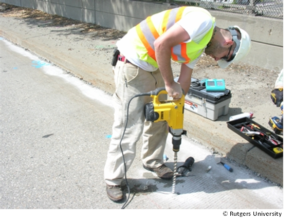
- Drill or core a 1 inch hole in the concrete to expose the reinforcement at each location where reinforcement has been located (figure 3).
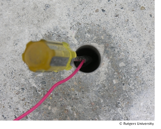
- Securely connect a lead wire to the reinforcement (figure 4).
- Check electrical continuity of the steel reinforcement cage between the installed lead wire locations (taps) by connecting the two taps to a standard multimeter and measuring the resistance. The reinforcement is considered continuous when the measured resistance is 1Ω or less considering the resistance of the lead wire.
- Securely connect the exposed steel to the reference electrode.
- Connect the reference electrode to the negative terminal and the steel reinforcement to the positive terminal of the high impedance voltmeter.
- Wet the contact sponge of the half-cell with soapy water to ensure good electrical contact with the concrete deck.
- If time and access allows, pre-wet the deck prior to testing.
- Place the reference electrode (wheel/rod) on each test point. Once the voltage has stabilized, the measurement can be made by moving the wheel along the grid (figure 5).
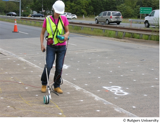
- The voltage values are stored in the data acquisition system or recorded by hand depending on the system being used.
- Once testing is complete, patch all tap locations with acceptable concrete materials (figure 6).
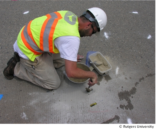
The ionic solution in the reference electrode must be replaced periodically according to the manufacturer recommendations.
Data Processing
No processing of HCP data is typically performed. Discrepancies in measurement accuracy may exist when there are extreme variations in the cover depth, and HCP measurements may need to be adjusted based on measuring deck electrical resistivity obtained at the same HCP test locations. However, in practice, data are generally gridded and mapped using contour-mapping software based on the measured HCP data.
Data Interpretation
Generally, x– and y-coordinates are plotted against measured voltage to produce a map showing areas of very high likelihood for active corrosion, very low likelihood for active corrosion, or a transition zone that spans the measurements in between. According to ASTM C876–09, Standard Test Method for Half-Cell Potentials of Uncoated Reinforcing Steel in Concrete, a measured potential more negative than -350mV corresponds to a 90 percent probability of active corrosion.(4) A measured potential less negative than -200mV corresponds to a 90 percent probability of no active corrosion. Corrosion activity is uncertain if the potential is in the range of -350mV to -200mV (figure 7). HCP data are typically used with other physical or chemical sampling or other NDE methods. These methods can be used jointly to determine the corrosion state that exists within a bridge deck. Many researchers have shown a good correlation between GPR and HCP maps or other more direct measures of a corrosive environment or active corrosion. It is important to understand that these values are not absolute and depend on the material and environmental conditions of the measured reinforced concrete element.
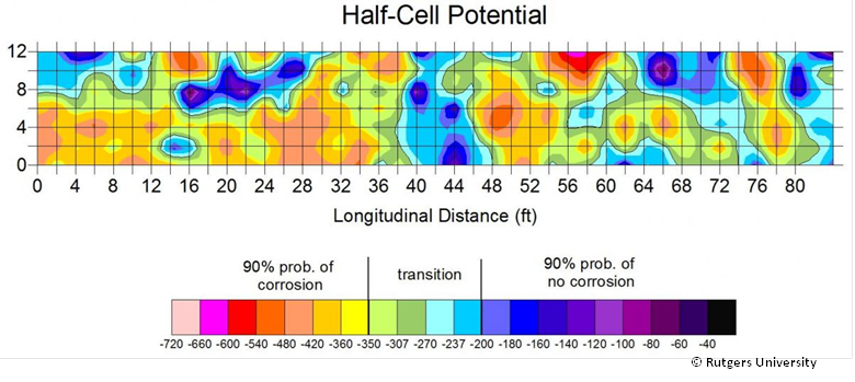
Potential Values.(2)
Advantages
- Rapid equipment setup, data collection, and data analysis.
- Easy to use with minimal training.
- Uncomplicated data processing; reduces to plotting the raw data.
- Economical.
- Moderately repeatable measurements.
- Correlates well with other NDE methods (GPR and electrical resistivity) and, to some extent, chemical sampling (chloride testing) to identify deck areas where corrosive environment and corrosion processes exist.
Limitations
- Erroneous or impossible measurements due to isolating layers (asphalt, coating, and paint) on the deck surface or decks with coated rebars.
- Cannot be conducted if electrical continuity does not exist in the element being evaluated.
- Does not directly measure corrosion rate or the extent of past corrosion (rebar section loss due to corrosion).
- Unreliable measurements when the concrete is wet, dense, or polymer-modified.
References
- Gucunski, N., et.al., Comprehensive Bridge Deck Deterioration Mapping of Nine Bridges by Nondestructive Evaluation Technologies, Project SPR-NDEB(90)-8H-00, Center for Advanced Infrastructure and Transportation, Rutgers University, January, 2011.
- Strategic Highway Research Program, “SHRP2 NDToolbox,” (Website), Washington, DC, Accessed online: February, 2015. http://www.ndtoolbox.org/content/bridges.
- Gucunski, N., et. al., Nondestructive Testing to Identify Concrete Bridge Deck Deterioration, Report S2-Ro6A-RR-1, SHRP2 Renewal Research, Transportation Research Board, 2013.
- ASTM, Standard, Standard Test Method for Half Cell Potentials of Reinforcing Steel in Concrete, C876, American Society for Testing and Materials, West Conshohocken.


