Bridge - Ground Penetrating Radar
Target of investigations
Ground penetrating radar (GPR) is beneficial in identifying the presence of subsurface features with dielectric constants different from the rest of the wood. Features include moisture pockets, knots, voids, and metal connectors. In particular, identifying moisture pockets is of high interest as moisture is associated with, or a precursor of, decay.
Description
GPR evaluates the condition of wood members by emitting short pulses of electromagnetic (EM) waves into the members and capturing part of the EM waves reflected from the interface of materials with different dielectric constants. The transmitter and receiver are typically placed in the same box, which enables the single-sided inspection of members.(1)
Physical Principle
As EM waves interact with materials of different dielectric constants, part of the waves is reflected toward the surface. The amplitude of reflection is affected by the extent of the differences between the dielectric constant of medium components. For example, because the dielectric constant of metals is considered infinite, the reflected EM signal off the metal surface is quite strong. Therefore, metallic components (such as bolts) can be easily observed in the GPR scans of wood members. Furthermore, EM waves lose their energy as they travel into a material. The extent of the energy loss depends on the frequency of EM waves and the nature of the material. For example, because water tends to substantially attenuate the EM waves, the penetration depth of EM waves in wet wood is limited.
Data Acquisition
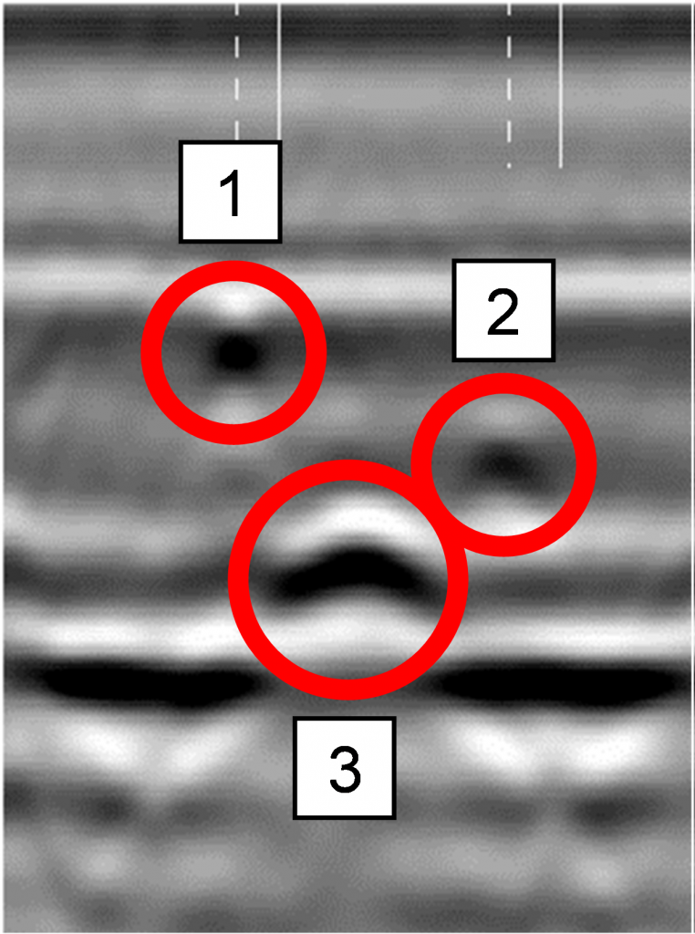
Unlike common nondestructive evaluation (NDE) techniques, GPR does not require measurements at multiple points, but rather it provides a continuous image from the internal structure of wood members. For GPR inspection, the equipment can be moved over the surface to quickly scan the area of interest.(1) While metallic bolts tend to generate strong reflections with hyperbolic shapes, a major challenge with GPR inspections is the difficulty in differentiating between different features as in figure 1.(2,1)

Figure 1. Graphic. A sample of GPR scan with various types of features: One and two are knots, and three is a drilled hole (to simulate void).(1)
For inspecting timber members, high-frequency GPR (1.5–2.5 GHz) is commonly used, although depending on the special application, a lower frequency GPR (i.e., 900 MHz to 1 GHz) may also be used. While a higher frequency antenna provides a higher resolution of GPR scans, the depth of penetration decreases with increasing frequency. For example, in a moist wood where EM waves tend to substantially attenuate, a lower frequency antenna is preferred.(2)
The depth of GPR penetration can be estimated by placing a metal plate, which acts as a strong reflector, on the far side of the member if both sides of a member are accessible.(2) The known distance of the metal plate from the antenna can also help estimate the depth of other features (i.e., voids) in GPR images. The application of GPR for condition assessment of wood members is still largely limited to the lab environment; however, some studies have applied GPR for inspection of wood in the field environment.(1)
Data Processing
Processing of GPR data is often accomplished using software provided by the GPR vendor. When parabolic shapes are present in the scans (i.e., as in figure 1), postprocessing can be performed to assess the velocity of EM waves in a timber member. This postprocessing enables estimating the depth of features such as voids, bolts, and so on. Alternatively, the data gathered from placing a metal plate at the other side of the member (known distance from antenna) can be used to estimate the velocity of EM waves inside the member. The raw GPR output is a time-history signal, and it does not provide information about the depth of penetration.
Postprocessing can also provide information about the amplitude of the signal at a certain depth and time. The postprocessing software allows exporting the amplitude of the GPR signal at multiple locations to a comma-separated value and text file.
Data Interpretation
The interpretation of data often requires GPR expertise. When the desired information is obtained from postprocessing, it may be plotted in the form of contour maps. Depending on the application, raw GPR signals can also be shown where features are marked (i.e., figure 1).
Advantages
GPR has several advantages, including:
- Rapid continuous member scanning.(2)
- One-sided access.(2)
- Repeatable results.(2)
- Scanning of imperfect surfaces.(2)
- Identifying subsurface features, such as moisture pockets, knots, voids, and metal connectors.
Limitations
- Postprocessing and interpretation of data can become complicated and may require NDE expertise.
- Differentiating between the different subsurface features can be difficult.
- Detecting small defects (i.e., fine cracks) is challenging.(2)
References
- Rodrigues, B. P., C. A. Senalik, X. Wu, and J. Wacker. 2021. “Use of Ground Penetrating Radar in the Evaluation of Wood Structures: A Review.” Forests 12 no. 4: 492.
- Riggio, M., R. W. Anthony, F. Augelli, B. Kasal, T. Lechner, W. Muller, and T. Tannert. 2014. “In Situ Assessment of Structural Timber Using Nondestructive Techniques.” Materials and Structures 47, no. 5: 749–766.


