Pavements - GPR (Thickness & Dowel Location)
Target of Investigation
Ground penetrating radar (GPR) can be used for a range of surface and subsurface investigation applications for concrete pavements. For condition assessment of the concrete surface course of pavements, GPR can be used for the following applications
- Location of dowels in jointed and plain concrete pavement.
- Measurement of the thickness levels of concrete pavement slabs.
Description
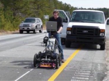
GPR testing is a widely used nondestructive evaluation technique for assessing concrete pavement slab thickness. Two types of GPR systems are available: air coupled (figure 1) and ground coupled (figure 2).

Figure 1. Photo. Air-coupled GPR system mounted on a vehicle.(3)

Figure 2. Photo. Data collection with a ground-coupled GPR system.(2)
Air-Coupled GPR
Air-coupled antennas are noncontact systems (i.e., they do not touch the surface during surveying). Air-coupled GPR systems are usually faster than ground-coupled systems; generally, they are used as a scanning tool to indicate locations where indepth testing with other systems (including groundcoupled GPR) is needed.(4)
Ground-Coupled GPR
Ground-coupled antennas, unlike air-coupled systems, must remain in contact with the surface while surveying. For concrete pavement with steel reinforcement or dowels, GPR can be used to detect reinforcing steel (rebars) and dowel locations and measure concrete cover depth. GPR signals are reflected at layer interfaces (including objects and defects) where different dielectric constants exist within the structure. The collected data are processed and analyzed to create a condition map of the structure or an image of the subsurface structure, including rebars and defects.
Physical Principal
GPR operates by sending discrete electromagnetic wave pulses (with a frequency range of
100–5,000 MHz) into a structure and then capturing the reflections from layer interfaces or other reflectors within the structure. Radar obeys the laws governing reflection and transmission of electromagnetic waves and is affected by the dielectric properties of the material: conductivity and the dielectric constant.(1) At each interface, part of the incident energy will be reflected back, and part will be transmitted beyond the interface. The ratio of reflected to transmitted energy depends on the contrast in dielectric properties of the materials on either side of the interface.
Air-Coupled GPR
As shown in figure 3, the largest peak of air-coupled GPR is the reflection from the pavement surface. The amplitudes before the direct couple are internally generated noise, and they should be removed from the trace prior to signal processing. Reflections that occur after the surface echo represent significant interfaces within the pavement, and the measured travel time is related to the depth of the layer or dowels. These reflections could be used to estimate the thickness of different layers of the pavement and dowels. Figure 4 is an equation to calculate layer thickness.

A. GPR propagation and reflection.

B. Multiple GPR A-scans.
Figure 3. Illustrations. Principle of air-coupled GPR for measuring pavement thickness.(5)

Where:
h1 = thickness of a layer.
c = speed of the radar wave in air.
Δt1 = time delay between two adjacent peaks.
εa = dielectric of the pavement surface.
Ground-Coupled GPR
The physical principles of ground-coupled GPR systems are similar to those for air-coupled GPR systems. Although slow compared to air-coupled systems, ground-coupled systems provide better depth penetration and a higher amount of readings. Thus, ground-coupled systems are better suited for indepth data collection and defining subsurface interfaces or defects.
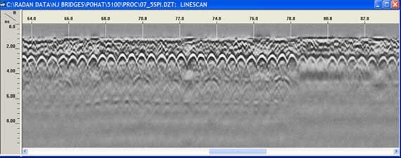
A GPR signal attenuates as it travels in a structure. Signal attenuation depends on geometric attenuation, signal scattering, reflections, and thermal losses. Two-way travel time and reflection amplitudes are recorded with a receiver antenna. When measurements are made over sequential survey points, they can be viewed as a GPR B-scan or profile (figure 5). The thickness of a layer within the structure can be calculated with the equation in figure 4. Rebars and dowels are seen as bright hyperbolas.

1 ft = 0.3 m.
Figure 5. Graph. Example GPR B-scan.
Data Acquisition
Manufacturers of GPR (air and ground coupled) recommend following their system-specific testing procedures when collecting data. These procedures are available in the user manuals supplied by manufacturers.
Data Processing
Data processing should be performed by personnel with extensive training and experience. Data processing can be done using analysis software. Preprocessing, which does not change the signal content of the original data, includes data channel splitting, data scaling, data reversing, and zero-level correction. Processing operations consist mainly of filtering operations and amplitude and dielectric value calculations. The primary objective of processing is to make GPR data more informative and easy to interpret. Figure 6 shows raw, preprocessed, and processed data. Software can be used to “pick” individual objects for analysis and to calculate the depth of suspected defects or layers using the two-way travel time.

A. Raw GPR data.

B. Preprocessed GPR data.

C. Processed GPR data.
Figure 6. Screenshots. Raw, preprocessed, and processed GPR data.(4)
Data Interpretation
Data interpretation should be performed by personnel with extensive training and experience. Layer thicknesses can be visible in GPR B-scan. Figure 7 is an example of a concrete pavement B- scan showing concrete pavement slab thickness and dowel locations. The peak of the hyperbola is approximately where the dowels are located.

1 m = 3.3 ft.
Figure 7. Graph. A GPR scan showing layer thicknesses and dowel locations in a concrete pavement.
Advantages
Advantages of GPR include the following:
- Well-established field data collection processes.
- Rapid test methods.
- Reliable and repeatable results.
Limitations
Limitations of GPR include the following:
- Air-coupled GPR systems should not be relied on to determine depths of defects.
- Extensive training and experience are required for operation, data processing, and data interpretation.
- Steel reinforcement mesh in the surface course may prevent signal penetration.
- Salts in concrete (from deicing operations or seawater) may cause signal penetration problems.
- External electromagnetic radiation (from cell phone, radio, and television antennas) can cause signal degradation.
References
- Gucunski, N., Imani, A., Romero, F., Nazarian, S., Yuan, D., Wiggenhauser, H., Shokouhi, P., Taffee, A., and Kutrubes, D. (2013). Nondestructive Testing to Identify Concrete Bridge Deck Deterioration, Report No. S2-R06A-RR-1, Transportation Research Board, Washington, DC.
- Heitzman, M., Maser, K., Tran, N.H., Brown, T., Bell, H., Holland, S., Ceylan, H., Belli, K., and Hiltunen, D. (2013). Nondestructive Testing to Identify Delaminations Between HMA Layers, Report No. S2-R06D-RR-1, Transportation Research Board, Washington, DC.
- Sebesta, S., Scullion, T., and Saarenketo, T. (2013). Using Infrared and High-Speed GroundPenetrating Radar for Uniformity Measurements on New HMA Layers, Report No. S2-R06C-RR-1, Transportation Research Board, Washington, DC.
- Wimsatt, A., White, J., Leung, C., Scullion, T., Hurlebaus, S., Zollinger, D., Grasley, Z., et al. (2014). Mapping Voids, Debonding, Delaminations, Moisture, and Other Defects Behind or Within Tunnel Linings, Report No. S2-R06G-RR-1, Transportation Research Board, Washington, DC.
- Arnold, J.A., Gibson, D.R.P., Mills, M.K., Scott, M., and Youtcheff, J. (2011). “Using GPR to Unearth Sensor Malfunctions.” Public Roads, 74(4), Federal Highway Administration, Washington, DC.


