Pavements - GPR (Asphalt Compaction Assessment)
Target of Investigation
Ground penetrating radar (GPR) can be used for surface investigation of asphalt pavements. In assessing the density of the hot mix asphalt (HMA) surface course, GPR can be used for the following applications:
- Measurement of uniformity of HMA density during construction.(1)
- Detection of segregation and mix densification.
A device that uses the GPR technology for the evaluation of pavement density is referred to density profiling system (DPS) that continuously measure asphalt compaction quality. DPS improves the measurement coverage over current quality assurance methods and mitigates destructive approaches.
Description
The density of asphalt concrete plays a significant role in long-term pavement performance. It has been shown that each 1% increase in air content beyond 7% ,leads to a 10% loss in pavement life .(2) Traditionally, cores at random locations were taken to investigate the asphalt concrete density. However, this process is labor-intensive, time-consuming, and provides information at discrete locations. Furthermore, selecting locations of coring, and the number of cores can be subjective. DPS is capable of providing continues HMA dielectric measurements that can be converted to the mat compaction level using calibration curves based on limited core data or plant mixed material samples. (3) A DPS can be deployed on a single or multiple GPR antennas and may carry by a push cart (figure 1) or a vehicle.

Figure 1. Photo. Data collection with a DPS.
DPS uses air-coupled GPR system that are noncontact (i.e., they do not touch the surface during surveying) and usually faster than ground-coupled systems.
Physical Principal
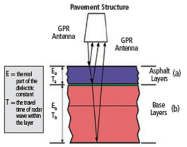
In general, GPR systems operate by sending discrete electromagnetic wave pulses (with a frequency range of 100–5,000 MHz) into a structure and then capturing the reflections from layer interfaces or other reflectors within the structure. Radar obeys the laws governing reflection and transmission of electromagnetic waves and is affected by the dielectric properties of the material: conductivity and the dielectric constant. (4) At each interface, part of the incident energy will be reflected back, and part will be transmitted beyond the interface. The ratio of reflected to transmitted energy depends on the contrast in dielectric properties of the materials on either side of the interface.
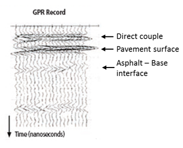
As shown in figure 2, the largest peak of air-coupled GPR is the reflection from the pavement surface. The amplitudes before the direct couple are internally generated noise, and they should be removed from the trace prior to signal processing. By using the signal reflected by the pavement surface, the dielectric constant of the surface can be estimated using the amplitude of signal reflected from the pavement surface and the signal reflected off a metal plate. An equation for calculating the dielectric of a HMA surface is presented in figure 3.

A. GPR propagation and reflection.

B. Multiple GPR A-scans

Where:
A1 = amplitude of reflection from the surface.
Am = amplitude of reflection from a large metal plate on the surface.
Data Acquisition
Manufacturers of DPS recommend following their system-specific testing procedures when collecting dielectric data of the field. These procedures are available in the user manuals supplied by manufacturers. AASHTO PP98-20 provides the equipment and software requirements for DPS testing. (6)
Data Processing
After collecting data from the field, the second step is to correlate the dielectric constant with the density of asphalt concrete. This step includes taking a few cores from regions of the field with low to high dielectric values, and then measuring the density of the cores in the laboratory. Subsequently, a calibration curve that relates dielectrics to densities of a paving project is developed. The calibration curve can be used to convert all dielectric data of the field to the density of asphalt concrete. AASHTO PP98-20 specifies calibration and verification procedures.(6) Recent developments propose procedures to create calibration curves using plant mix material samples.(3)
Data Interpretation
The dielectric value of an asphalt pavement that was measured using a 2.0-GHz air-coupled GPR antenna is depicted in figure 4. Quality control can be performed based on the relationship between the dielectric value and air-void ratio for in-place HMA.(3) A low dielectric value usually indicates a large air-void ratio in HMA.

1 ft = 0.3 m.
Figure 4. Graph. Dielectric value of an asphalt pavement.(3)
Advantages
Advantages of DPS GPR include the following:
- Well-established field data collection processes.
- Real-time compaction and density data for the entire paving project.
- Rapid test methods.
- Reliable and repeatable results.
Limitations
Limitations of GPR include the following:
- Moisture on the surface of asphalt may cause changes in acquired dielectric values and bias in calibration curves.
- External electromagnetic radiation (from cell phone, radio, and television antennas) can cause signal degradation.
References
- Sebesta, S., Scullion, T., and Saarenketo, T. (2013). Using Infrared and High-Speed Ground-Penetrating Radar for Uniformity Measurements on New HMA Layers, Report No. S2-R06C-RR-1, Transportation Research Board, Washington, DC.
- Linden, Robert N., Joe P. Mahoney, and Newton C. Jackson. (1989). “Effect of compaction on asphalt concrete performance.” Report No. 1217, Transportation Research Board, Washington, DC.
- Hoegh, Kyle, et al. “Minnesota Department of Transportation Case Studies for Coreless Asphalt Pavement Compaction Assessment.” Transportation Research Record 2674.2 (2020): 291-301.
- Gucunski, N., Imani, A., Romero, F., Nazarian, S., Yuan, D., Wiggenhauser, H., Shokouhi, P., Taffee, A., and Kutrubes, D. (2013). Nondestructive Testing to Identify Concrete Bridge Deck Deterioration, Report No. S2-R06A-RR-1, Transportation Research Board, Washington, DC.
- Arnold, J.A., Gibson, D.R.P., Mills, M.K., Scott, M., and Youtcheff, J. (2011). “Using GPR to Unearth Sensor Malfunctions.” Public Roads, 74(4), Federal Highway Administration, Washington, DC.
- Asphalt Surface Dielectric Profiling System Using Ground Penetrating Radar. AASHTO PP 98-20. AASHTO, Washington, D.C., 2020.


