Bridge - Galvanostatic Pulse Measurement (GPM)
Target of Investigation
GPM is used to estimate the corrosion rate of steel in steel-reinforced concrete structures. The corrosion rate is very important for determining how fast a concrete member is deteriorating; this determination is not possible with either the ER or HCP technologies. GPM is also advantageous in corrosion risk assessment over HCP measurement in situations when concrete is wet, dense, or polymer-modified, and thus the access to oxygen is limited.(1)
Description
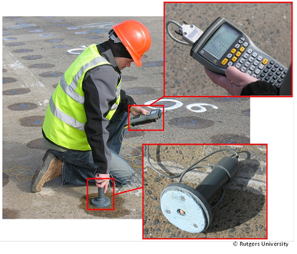
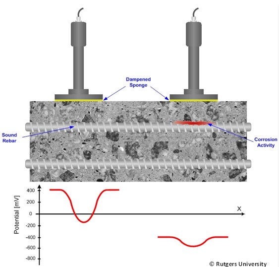
GPM is an electrochemical NDE technology used for rapid assessment of rebar corrosion, primarily to estimate the corrosion rate for steel rebars. GPM is based on the polarization of rebar using a small current pulse and measurement in the potential change.(2) GPM uses an electrode device positioned on a concrete surface and a reference electrode attached directly to the steel reinforcement to determine the half-cell potential, corrosion rate, and resistance between the reinforcement and device (figure 1).

Physical Principle
The GPM corrosion assessment is based on the measurement of the current required to change the potential difference between the reinforcement and a standard reference electrode. The current is a result flow of electrons from the anodic and cathodic sides in concrete. The anodic side is a corroding rebar where there is surplus of electrons on the base metal as a result of releasing metal ions into an electrolytically conducting liquid. Those excess electrons flow to a cathodic side, concrete with oxidizing agents in the liquid, inducing a corrosion current between the two sides. Knowing the current and voltage allows an inspector to determine the polarization resistance, which is related to the rate of corrosion. The GPM test is conducted by first applying to counter electrode a number of anodic DC pulses (5-400µA). The first, stronger pulse is between 3 to 60 seconds, and its intensity will primarily depend on the properties of the object under investigation. Several smaller consecutive pulses of gradually increased intensity may follow the first pulse. The objective of applying DC pulses is to obtain a sufficiently high polarization, at which point potential variations are recorded by means of a reference electrode (figure 2). Noncorroding or passive reinforcement possesses no current and thus will have a high resistance to current flow which is reflected in a potential shift of around 100 mV.(3) Active corrosion is likely when the potential shift gets smaller. This can be also explained as an actively corroding system can quickly compensate for a removal of electrons due to the corrosion reaction or polarization achieved by the current pulse remains low in an actively corroding area.

Data Acquisition
For data collection using the galvanostatic pulse method on concrete pavement, follow the procedure described in ASTM C876-09, Standard Test Method for Corrosion Potentials of Uncoated Reinforcing Steel in Concrete. The procedure is summarized as follows:(4)
- Identify points or lay out a grid for data collection on the pavement, ensuring that points are not so close together that measurements overlap and are not so far apart that localized corrosion is missed.
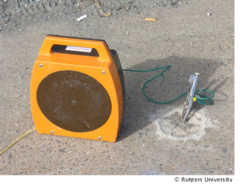
- Electrically connect the reinforcing steel to the positive lead of the system (figure 3). The following are typical steps to accomplish this procedure:
- Locate the steel using a rebar locator, drill down to the reinforcement, and connect a lead wire to the steel using a self-tapping screw drilled into the rebar.
- Ensure all measurement locations are electrically continuous with this tap.
- Confirm that the entire survey area is covered; this may require multiple taps and corresponding measurement areas.

Figure 3. Photo. Electrical connection to exposed reinforcement steel.(1)
- Electrically connect the reference electrode to the negative lead of the system.
- Wet the contact sponge of the reference and counter electrodes to ensure good electrical contact with the concrete pavement; prewetting can also be used if conditions allow. The following steps describe the prewetting process:
- Wet the entire surface of the testing locations but make sure no free surface water remains between test locations before taking measurements.
- Place a prewetted sponge on each test location before taking measurements and leave it in place for the duration of collection at that location.
- Place the reference electrode on the test point (figure 4).

Figure 4. Photo. Data collection with galvanostatic pulse system.
- Adjust the current pulse amplitude with one strong and then several shorter pulses until the reinforcing steel reaches a sufficiently high polarization.
- Record the potential variations using a handheld computer with data acquisition software.
- Move to the next test point and repeat the collection procedure.
- After testing is completed, patch all tap locations.
Data Processing
Typically, no processing is performed for data collected using the galvanostatic pulse method. The system usually has contour-mapping software for gridding and plotting data for visualization purposes. The slope of the potential–time curve measured during the current pulse can be used to provide information about the corrosion state of the steel reinforcement, and the potential data can be used to obtain a measure of the concrete ER for a given concrete cover depth.
Data Interpretation
Figure 5 and figure 6 are typical contour maps from a galvanostatic pulse method survey. Figure 5 is an ER map that shows values ranging from 5 to 63 kΩ. Areas with lower ER values indicate a higher probability of a corrosive environment from the intrusion of moisture, chlorides, and salts in the concrete. Areas with higher ER values indicate a noncorrosive environment.

1 ft = 0.3 m.
Figure 5. Contour map. Concrete ER from a galvanostatic pulse method survey.(5)
From the corrosion rate, cross section loss can be estimated using Faraday’s law of electrochemical equivalent. Figure 6 shows cross section loss assuming that a corrosion rate of 1 μA/cm2 (6.45 μA/inch2) corresponds to a cross section loss of about 11.6 μm/yr (0.457mils/yr) for carbon steel.

1 ft = 0.3 m; 1 μm = 0.039 mils.
Note: Black indicates no data for those areas.
Figure 6. Contour map. Estimated section loss based on corrosion rates from a galvanostatic pulse method survey.(5)
The obtained corrosion rate is an instantaneous average value. A more detailed knowledge of the daily and seasonal changes in the corrosion rate is required to obtain lifetime predictions of service life and condition. The data obtained from the galvanostatic pulse method survey should be combined with data from other nondestructive tests and other investigations to determine concrete integrity and penetration rates.(1)
Advantages
Advantages of the galvanostatic pulse method include the following:
- Calculates reinforcement steel corrosion rates.
- Obtains HCP and ER measurements.
- Requires low to medium level of expertise to operate data collection equipment.
- Does not require much data processing.
Limitations
Limitations of the galvanostatic pulse method include the following:
- Requires electrical connectivity to reinforcing steel throughout test area.
- Gives unstable measurements when ER of the concrete cover is high.(1)
- Requires a few minutes for stabilization of potential before measurements can be recorded.(1)
- Is time consuming and labor intensive for large survey areas.
- Cannot be used with epoxy-coated reinforcing steel.(4)
References
- Gucunski, N., Imani, A., Romero, F., Nazarian, S., Yuan, D., Wiggenhauser, H., Shokouhi, P., Taffee, A., and Kutrubes, D. (2013). Nondestructive Testing to Identify Concrete Bridge Deck Deterioration, Report No. S2-R06A-RR-1, Transportation Research Board, Washington, DC.
- Federal Highway Administration. (2016). “Nondestructive Evaluation Laboratory: Equipment.” (website) Washington, DC. Available online: https://highways.dot.gov/laboratories/nondestructive-evaluation-laboratory/laboratory-equipment, last accessed April 10, 2016.
- Germann Instruments. (n.d.) “All products.” (website) Evanston, IL. Available online: http://germann.org/all-products, last accessed March 5, 2019.
- ASTM C876-015 (2015). “Standard Test Method for Corrosion Potentials of Uncoated Reinforcing Steel in Concrete.” Book of Standards 03.02, ASTM International, West Conshohocken, PA. Strategic Highway Research Program. (n.d.) “SHRP2 NDToolbox.” (website) Washington, DC. Available online: https://www.fhwa.dot.gov/goshrp2/Solutions/Operations/R06/NDToolbox, last accessed


