Bridge - Electrical Resistivity (ER)
Target of Investigation
Electrical resistivity can be used to determine the following:
- Reinforced concrete’s susceptibility to corrosion.
- Regions susceptible to moisture and chloride penetration.
Resistivity measurement can be used in tandem with other corrosion assessment techniques such as half-cell potential, which identifies corrosion activity, to provide a more comprehensive assessment of corrosion.
Description
The presence and concentration of water, chlorides, salts, and other corrosive substances significantly contribute to a corrosive environment in concrete. The electrical resistivity method can be used to evaluate the existence of such corrosive environment. Damaged and cracked areas, due to increased porosity, will form preferential paths for fluid and ion flow. This will lead to higher moisture and chloride concentrations and higher concrete electrical conductivity, manifesting as a lower electrical resistivity. The lower the electrical resistivity of the concrete, the higher the current passing between anodic and cathodic areas of the reinforcement steel will be.(1) Several studies have established approximate relationships between the electrical resistivity and the corrosion rate of steel reinforcement (table 1).
Table 1. Electrical Resistivity and Corresponding Corrosion Rates for Steel-reinforced Concrete.(1)
| Electrical Resistivity (KΩ*cm) | Corrosion Rate |
|---|---|
| < 5 | Very High |
| 5 – 10 | High |
| 10 – 20 | Moderate – Low |
| > 20 | Low |
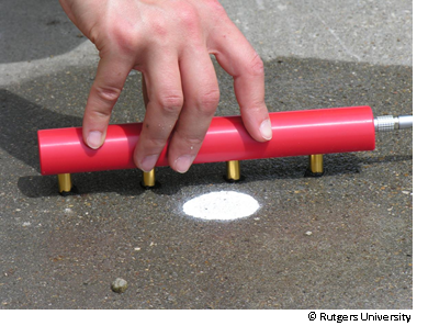
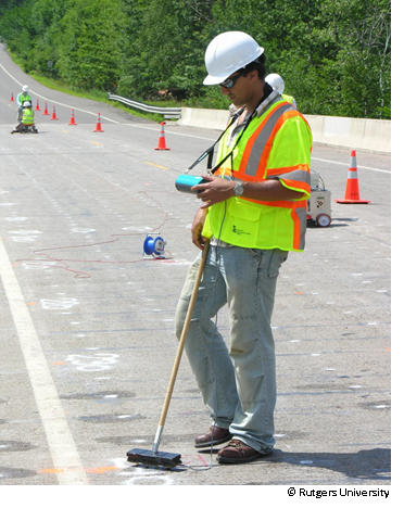
The Wenner probe is a commonly used electrical resistivity probe (figure 1). The probe has four electrodes. Figure 2 shows electrical resistivity measurement being conducted on a concrete bridge deck.


Physical Principle
Electrical resistivity or its reciprocal, electrical conductivity, is an intrinsic property that quantifies the ability of a given material to oppose or conduct electric current. The standard SI unit of electrical resistivity is ohm-meter (Ω–m) although other units like ohm-centimeter (Ω–cm) are also used. Surface electrical resistivity of a steel-reinforced concrete element (typically, the cover of a steel-reinforced concrete slab or deck) is an indicator of concrete corrosive environment.
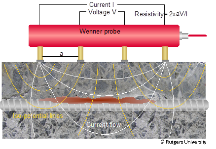
To conduct electrical resistivity tests, the voltage and current are measured at the surface of the object under investigation using a certain layout of electrodes. The most simple and common electrode layout in civil engineering applications is the Wenner array (figure 3). The Wenner array uses four in-line electrodes that are equally spaced.(1) A current is applied between the two outer electrodes, and the potential is measured across the two inner ones. The resistivity is then calculated (figure 4).


Where:
ρ = Resistivity (Ω–m or Ω–cm).
α = Electrode separation (m).
V = Voltage (V).
I = Current (amp).
Building materials such as concrete, cement, or wood are ion conductors, which means that electrical conduction happens through the interconnected pore space. The resistivity of fully saturated concrete is between 1 and 10 kΩ-cm, depending on the conductivity of the pore fluid. When concrete is oven dried, its electrical resistivity can be 100 kΩ-cm or more, causing it to act as an insulator. The electrical resistivity of concrete affects the ionic current flow between the anode and cathode and the rate at which corrosion can occur. Dry concrete has high electrical resistivity and, thus, will impede the current flow and inhibit corrosion, whereas highly permeable and moist concrete has low electrical resistivity and a high likelihood of corrosion. As concrete is a composite material, its electrical resistivity will always depend upon its porosity, pore size distribution, cement chemistry, water/cement ratio, and types and concentrations of admixtures. The resistivity is also a function of the ion type and content of the saturation fluid.(3,4). Drying the concrete surface, carbonation, and the presence of steel reinforcement in the vicinity of the electrodes significantly affect resistivity measurements.
Data Acquisition
Currently, there is no ASTM or other standard for measuring resistivity of concrete using a Wenner array. ASTM G57-06, Standard Test Method for Field Measurement of Soil Resistivity Using the Wenner Four-Electrode Method, is a similar application to concrete testing, but there are differences.
For electrical resistivity measurements, galvanic contact has to be ensured between the electrodes and the concrete. If the surface of concrete is dry, the concrete has to be pre-wetted with water, contact graphite gel, or pastes, or the electrodes must be kept moist.
The following steps explain the general procedure for electrical resistivity measurements:
- A 2-ft by 2-ft survey grid is laid out on the surface of concrete deck. Each grid point is used as the central point of a Wenner probe.
- The sponges on all four electrodes are fully saturated with soapy water to assure electrical coupling between the electrodes and concrete.
- The spots for electrodes sitting on a concrete surface are wetted by soapy water before the electrodes are placed on it to ensure good contact between the electrodes and the concrete surface. The key is to keep the sponges wet all the times.
- The resistivity values are measured and stored in a control unit.
Data Processing
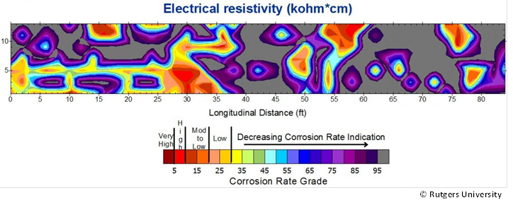
Data processing is simple and consists of generating a contour map of the measured electrical resistivity data to report the spatial distribution of the resistivity values.
Data Interpretation
Areas with low resistivity describe highly corrosive environment facilitating high corrosion rates, whereas areas with a high resistivity describe an environment that does not facilitate corrosion. In Figure 5, the electrical resistivity is correlated to the corrosion rate according to Table 1 (See Description).

Advantages
- Low to medium level of expertise required for equipment setup and data collection.
- Low-cost testing.
- Simple data processing and presentation.
- Testing is repeatable with low coefficient of variation.
Limitations
- Not a direct measurement of corrosion, like corrosion rate or corrosion activity.
- Time consuming and labor intensive on large bridge decks since data collection is often done manually.
- Challenging data interpretation since ER is impacted by a number of environmental parameters (e.g., moisture and salt content, porosity), and their impacts on the measured data cannot be delineated.
- Measurements on concrete elements with electrically isolating coatings or overlays, like asphalt overlays on bridge decks, provide meaningless results.
References
- Gucunski, N., et. al., Nondestructive Testing to Identify Concrete Bridge Deck Deterioration, Report S2-Ro6A-RR-1, SHRP2 Renewal Research, Transportation Research Board, 2013.
- Gucunski, N., et.al., Comprehensive Bridge Deck Deterioration Mapping of Nine Bridges by Nondestructive Evaluation Technologies, Project SPR-NDEB(90)-8H-00, Center for Advanced Infrastructure and Transportation, Rutgers University, January, 2011.


