Bridge - Eddy Current Testing (ECT)
Target of Investigation
ECT is used to detect cracks in steel bridge members. Due to the magnetic properties of steel, only surface breaking or near surface-breaking cracks can be detected. The technology can be effective for detecting cracks in welds; however, special probes must be used due to complex magnetic and microstructural properties associated with the weld and the surrounding heat affected zone (HAZ).
Description
ECT works by scanning a small electromagnetic probe across the surface of a material. The signal produced by the probe is displayed in real-time on an instrument screen, and changes in the signals are produced when the probe scans across a discontinuity in the material. Inspectors interpret the changes in the signal produced by the probe to identify cracks or other defects.
The ECT method is used to inspect conductive materials to detect surface or near-surface cracks. ECT is used to detect cracks in a wide variety of metal components, such as airplane landing gear, turbine engines, heat exchanger tubing, pipes, and rods. For bridges, ECT is applied to detect surface-breaking cracks in steel components.
Physical Principle
The basic principle of ECT is to induce electrical currents in a conductive material and analyze perturbations in the current flow caused by discontinuities in the material. The induced currents flow in a circular pattern and are referred to as eddy currents. Eddy currents are generated by a probe consisting of one or more wire coils excited with alternating currents at a regulated frequency. This results in a dynamic expanding and collapsing magnetic field surrounding the coil. When an electrically conductive material is placed within the magnetic field, eddy currents are induced in the material through electromagnetic induction. The currents flowing in the material create a secondary magnetic field that opposes the primary magnetic field of the coil, affecting the impedance of the coil. The presence of a discontinuity, defect, or irregularity in the grain structure of the material disrupts the flow of the current in the material; therefore, changes in the impedance of the coil are produced. Impedance changes in the coil are analyzed and interpreted to detect defects in the material.
Probes must be oriented such that a crack is perpendicular to the flow of current in the material and the crack interrupts the current flow. Current flow in the material is parallel to the flow of current in the probe coil with current flow in the opposite direction. In other words, the path of current at the surface of the material is an “image” of the coil with opposing current direction.
The sensitivity of eddy current inspection depends on the eddy current density at the flaw location. Eddy current density decreases with increasing depth into the material under test due to the skin effect. The depth of penetration decreases with increasing frequency, conductivity, and magnetic permeability.
The density of currents in a conductive material can be described by the standard depth of penetration equation (figure 1), which determines the depth into the material at which the density of current is reduced to 1/e (i.e., ~37 percent) relative to the density at the surface.
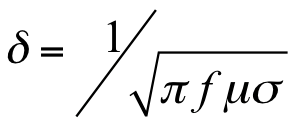
Where:
d = skin depth of penetration (mm).
f = excitation frequency (Hz).
m = magnetic permeability (H/mm).
s = electrical conductivity (%IACS).
IACS = International Annealed Copper Standard.
When attempting to locate flaws, a frequency is selected that places the expected flaw depth within one standard depth of penetration into the material; this ensures the density of current in the material is sufficient to affect the impedance of the coil and produce a flaw indication. For ferromagnetic materials (e.g., steel), permeability values are high; as a result, the standard skin depth is very small, typically less than 1-3 mm depending on the frequency used. ECT in steel can detect only surface-breaking cracks or near surface-breaking cracks. Non-ferromagnetic materials (e.g., aluminum) have a relative permeability of approximately 1 mm; therefore, skin depths are larger and subsurface flaws may be detected.
ECT is sometimes used to determine the conductivity of materials or to differentiate one metal from another based on the electrical properties of the material. For this application, the test frequency is often set such that three times the standard skin depth calculated from the preceding equation is less than the thickness of the material. This ensures the material boundaries will not affect the ECT because current density is reduced to 1/e3 (~5 percent) in the area of the boundary.
The density of current in the material depends on the intensity of the magnetic field inducing the current. Magnetic fields attenuate exponentially in air, such that the distance from the probe coil to the surface of the material under test is an important test parameter. This effect is referred to as the “lift-off factor”—the loss in signal strength resulting from the distance between the probe coil and the surface of the material under test. In general, uniform and very small lift-off values are preferred for achieving better detection sensitivity to flaws. For steel bridges, coating on the steel causes lift-off of the sensor, decreasing signal intensity relative to uncoated steel. This affect can be mitigated by proper calibration that includes similar lift-off of the probe from the surface of the material.(1,2)
Data Acquisition
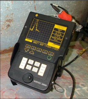
Data acquisition for ECT includes an ECT instrument and an appropriate hand-held probe. Relatively low cost, battery-operated portable instruments are available that make the technology practical for use on bridges (figure 2). Test results are displayed on the ECT instrument in real-time for interpretation in the field.
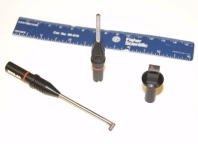
ECT probes are produced in a variety of configurations suitable for different applications. Several typical probes are shown in figure 3. Probes with right-angle heads are designed for inspecting the inside of bolt holes (figure 3, left). For example, very small probes are designed for applications where access is limited (figure 3, center). For inspection of welds, a differential probe with two probe coils is typically used (figure 3, right) that reduces the effect of material property variations on the probe output.
Data Processing
Minimal data processing is required for ECT because the impedance signal is analyzed directly to detect cracks. Analog frequency and time-based filters are commonly used to improve signal quality.
Data Interpretation
An operator completes the interpretation of data from ECT in real-time during an inspection. The signal output is analyzed as the probe is scanned across the surface of the material. The signal is analyzed to determine if signal variations represent a relevant indication, such as a crack, or if signal variations represent non-relevant indications, such as probe lift off, non-crack surface irregularities, or material property variations.
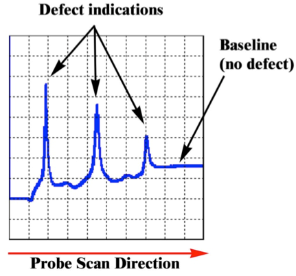
Data are plotted using an impedance plane display or a time series display. An impedance plane display plots the individual components of the impedance signal (reactance and resistance) as x–y coordinates. A time series display plots the individual components of the impedance separately against a time, sample number, or distance axis. Figure 4 shows an example of a time series display in which the probe resistance is plotted against a distance axis. The signal shown in figure 4 results from scanning the probe over a specimen with three EDM notches of different depths, and illustrates the signal displacement observed by the operator as the probe is scanned across each notch. Figure 5 shows a pencil ECT probe being used to inspect the web of a girder.
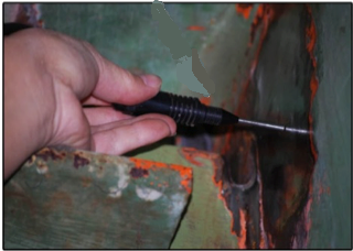
Signal output can be dependent on the movement of the probe over the specimen surface. Irregular surfaces or inconsistent movement of a probe (e.g., lifting the probe off the surface or tilting the probe) can produce signals that may be interpreted as defects. Skilled operators can consistently scan specimens and use judgment to determine the nature of the output signal.
Advantages
- Low-cost, portable instrumentation.
- Minimal surface preparation.
- Does not require coating removal like other crack detection technologies such as dye penetrant testing (PT), ultrasonics (UT), or magnetic particle testing (MT).
- Can detect paint thickness variations.
Limitations
- Detects only surface-breaking cracks.
- Magnetic properties of weld materials can influence results.
- Method requires skill by the operator in order to obtain reliable results.
References
- American Society of Nondestructive Testing (ASNT) Handbook, 3rd Edition, Vol. 5, 2005.
- Hagemaier, J.D., Fundamentals of Eddy Current Testing, December, 1990.


