Tunnel - Eddy Current Array Testing (ECA)
Target of Investigation
The eddy-current array testing method is used to inspect conductive objects to detect surface or near-surface defects. It has a variety of industrial applications, such as in the aerospace and petrochemical industries. ECA is very flexible, and a wide range of specimen shapes can be inspected. For bridge structures, ECA is carried out on ferromagnetic steel welds to inspect for defects and can be used for testing over typical bridge paints. ECA can also be used to estimate geometric parameters such as lift-off, coating thicknesses, and other dependent properties such as stress, related to either magnetic permeability or electrical conductivity, and temperature, related to electrical conductivity.(1)
Description
The ECA is a newer technology that extends the principle of conventional eddy current testing (ET). ECA systems are generally made of a conformable eddy current array specifically designed for model-based inverse methods. Multivariate inverse methods convert the sensor response into absolute property estimates. Multiple sensor responses for each individual sensing element at each location are converted into estimates of several material properties at each location along the inspected surface of the material.
Physical Principle
ECA is conceptually similar to conventional ET. For conventional ET, eddy currents are induced when an energized probe-coil is placed near the surface of a conductive material; ECA extends this concept and uses an array of multiple coils instead of only a single coil. The coil current must be alternating current (AC) since a time-dependent magnetic field is required to induce or generate electrical currents. The eddy currents induced at the surface of the test material are time varying and have magnitude and phase. Eddy currents are proportional to the electrical conductivity of the material. Material properties and discontinuities such as cracks disturb the eddy current trajectories, affecting the magnitude and phase of the induced current. The coils sense the magnetic field induced by these currents, producing a complex voltage in the coils.
Data Acquisition
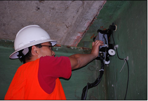
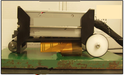
Sensor arrays are fabricated on a thin flexible printed circuit board substrate. This allows sensors to conform to the shape of a specimen. Data acquisition consists of electronics to drive sensor arrays and measure the response of the individual array coils (figures 1 and 2).
Sensor arrays can measure multiple quantities, such as lift-off (distance from the array coil to the specimen), permeability, and other material properties. Sensor coils can be incorporated with encoders to measure the movement of the coils and correlate measured data with spatial position on a specimen. Equipment is generally designed for laboratory and industrial applications.


Data Processing
Data processing is done internally within the instrument hardware and software. System software uses calibrated look-up tables to relate measured signals to desired physical parameters. With the use of position encoders, data can be presented with a spatial reference. Data can be stored for offline processing and provides a permanent record.
Data Interpretation
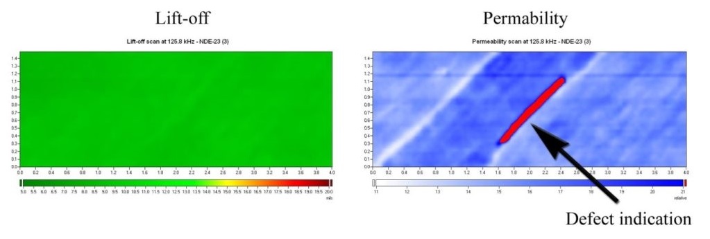
Data is interpreted by the operator while using the device. Signal output is observed on the instrument display and the operator uses judgment to determine the meaning of the signal. Operating equipment and interpreting data requires significant skill for an operator. Figure 3 shows sample ECA testing results for estimating lift-off and magnetic permeability.

Signal output can be dependent on the movement of the probe over the specimen surface. Irregular surfaces or inconsistent movement of a probe (e.g., lifting the probe off the surface or tilting the probe) can produce signals that could be interpreted as defects. Skilled operators can consistently scan specimens and apply judgment as to the nature of the output signal.
Advantages
- Can detect near-surface defects through paint.
- Provides a C-scan type of image of a defect.
- Can measure multiple physical parameters.
- Can compensate for lift-off and material property variations better than conventional eddy current.
Limitations
- Results influenced by magnetic properties of weld materials.
- Results affected by probe orientation during scanning.
- Requires operator experience and skill.
- Costly equipment.
- Limited use in difficult access areas due to probe size.
References
- ASTM, Standard Guide for Eddy Current Testing of Electrically Conducting Materials Using Conformable Sensor Arrays, E2884-13e1, ASTM International, Conshohcken, PA, 2013.


