Bridge - Crack Propagation Gage (CPG)
Target of Investigation
CPGs are applied to monitor the extension of a crack in steel girders, eyebars, and truss members. Cracks detected using other methods, such as visual inspection, can be monitored with the gages to evaluate if the crack is growing. Fatigue cracks in a steel girder can be monitored with CPGs to monitor the rate at which the crack is growing as a result of the applied loading.
CPGs can also be used to monitor localized areas of a structure where cracking is likely to develop. In this way, the gage can be used as a crack detection tool that monitors the area continuously to determine if a crack develops.
Description
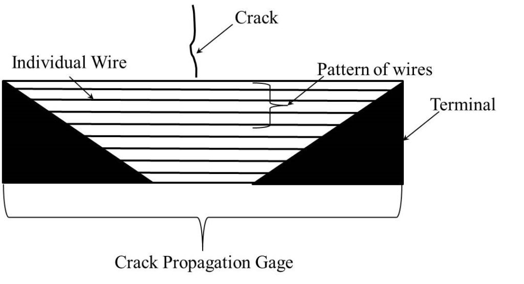
A CPG consists of a series of conductive tracks etched on a polymer substrate. The gage is bonded to the surface of a specimen in the area of the crack tip such that growth of the crack will result in individual tracks in the gage being fractured, affecting the resistance of the gage.
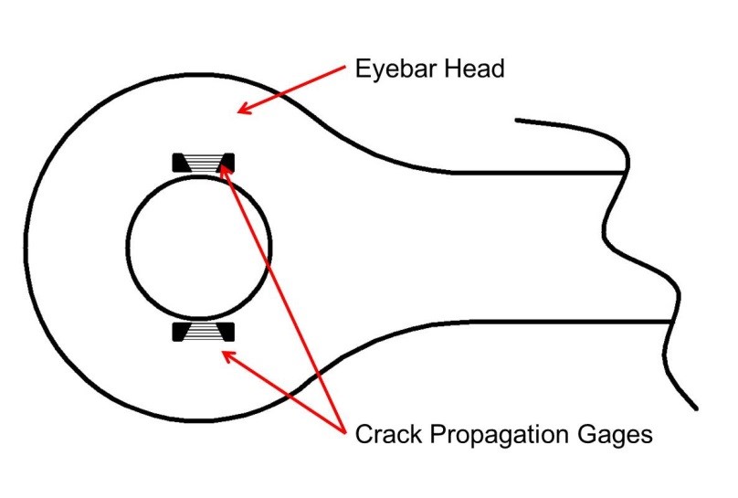
Figure 1 shows a schematic diagram of two CPGs mounted on the surface of an eyebar. The gages are mounted on the eyebar head in the area where cracks initiating at the bore of the eyebar would be expected to grow through the eyebar head. In this way, the gage acts as a crack detection sensor that produces a resistance change if a crack develops in the area under the gage.

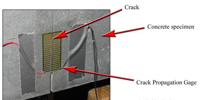
CPGs are available is a variety of different sizes and shapes. For example, gages with circular or semi-circular shapes are produced for monitoring cracks initiating at bolt holes. Rectangular-shaped gages (figure 2) are available in a variety of different sizes and are typically used for monitoring cracks in plates. Gages are bonded to the surface using an adhesive. Surface preparation is required to ensure sufficient bonding between the gage and the surface such that crack growth will result fracture of the conductive tracks.

Physical Principle
CPGs are used to measure the growth of a surface-breaking crack. The sensor consists of a pattern of conductive tracks etched on a non-conductive polymer substrate. The gage is bonded to the specimen surface at the tip of a crack (figure 3). When the crack length increases, the individual tracks in the sensor gage are fractured, causing the resistance of the gage to increase. A simple voltage or resistance measurement across the terminals on the gage indicates the number of tracks that are fractured, and these changes are interpreted to determine the crack growth.(1)

Data Acquisition
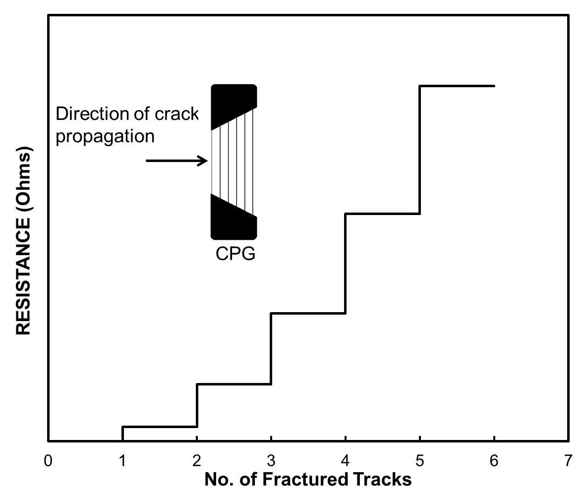
The data produced by a CPG is a voltage or resistance measurement based on the resistance of the gage. The resistance of the gage increases when individual conductive tracks are fractured by a crack propagating across the gage. Instrumentation to read a CPG can be as simple as an ohmmeter with milliohm sensitivity to measure the resistance of the gage directly. Common data acquisition systems can also be used to monitor the voltage output of the gage. Data is typically collected during a long time intervals, such as weeks or even years, depending on the anticipated rate of crack growth. CPGs can be installed on a permanent basis to monitor an area where cracks are anticipated. Figure 4 illustrates the typical output of a CPG. The gage pattern shown has six individual conductive tracks extending between terminals at each end. Voltage or resistance measurements across these terminals indicate the number of tracks that have fractured. As the crack propagates in the material being tested, the conductive tracks of the CPG are fractured, resulting in an increase in the resistance between the terminals on the gage.

Data Processing
A CPG produces a voltage or resistance that changes as a result of crack propagation, therefore little data processing is required.
Data Interpretation
The data produced from a CPG is a change in the resistance of the gage, interpreted to determine the length of crack extension.
Advantages
- Low cost.
- Simple application.
- Easy data interpretation.
- Provides continuous monitoring of crack growth.
Limitations
- Cracks must be surface breaking.
- Requires surface access.
- Requires surface preparation.
References
- ASTM, Standard Test Method for Measurement of Fatigue Crack Growth Rates, E647-13ae1, ASTM International, West Conshohocken, PA, 2013.


