Underground Utilities - Cable and Pipe Locators — Fiber Optics
Target of Investigation
Cable and pipe locator tools are nondestructive evaluation (NDE) technologies that detect and identify buried cables and pipes based on the measurement of electromagnetic (EM) signals emitted by them. The construction and utility service industries often rely on these relatively easy-to-use instruments to locate subsurface features. These systems are generally portable and cost effective and provide an operator with clear, instantaneous feedback for marking and mapping utility lines ahead of construction or maintenance operations.
Description
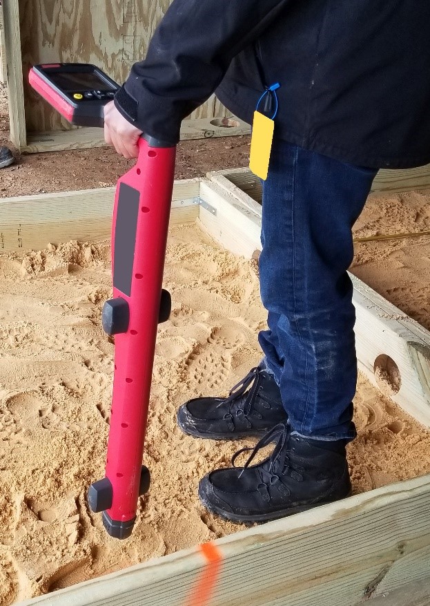
Like any other NDE method, a cable and pipe locator uses a transmission source, a receiver unit, and a data-acquisition system to organize, present, and even interpret the incoming signals from the receiver instrument. For these locator tools, the transmission source differs depending on the detection method used. Passive detection relies on the utility line to generate an EM signal for detection. In contrast, active detection calls for the system instrumentation to transmit an EM signal into the line to induce a response for detection. The receiver instrument is usually a hand-held device with an antenna-like arrangement of wiring encased in a protective plastic casing to receive and amplify incoming EM signals. The data-acquisition system will generally be integrated into the receiver device, providing a visual display of the automatically processed signals for the operator and an audible tone to indicate proximity to a buried utility (figure 1).

Physical Principle
Electrical current traveling along a conducting material, such as the copper in a wire, creates EM fields, which can induce electrical currents in other conducting materials. Cable and pipe locators apply this concept to the transmission source and receiver. For passive detection, the transmission source is the buried utility line, where the current flowing through the line produces an EM field. This method requires the cable or pipe to be actively powered with current flowing through it, as in the case of buried power lines. However, passive detection is not possible for any unpowered utility lines, such as water or sewer lines, generally, and power lines when current is not flowing. These situations require active detection.
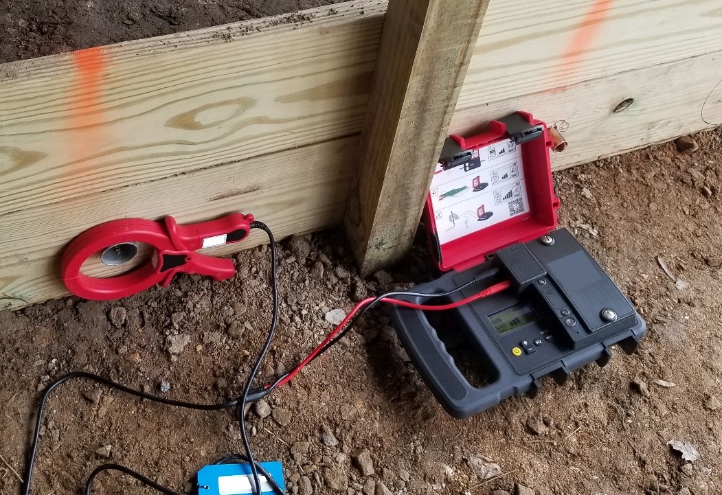
For active detection, the transmission source is an external signal transmitter system that generates its own EM field to induce a current in the target utility line, which then reciprocally generates an EM field to be detected by the receiver in the cable locator. The signal transmitter system can be integrated into the cable locator tool using a standalone transmitter box placed on the ground or a clamp system (figure 2) physically connected to a surface-accessible location on the buried utility line for induction and current generation. Where passive detection can only locate actively powered utility lines, active detection can also locate any utility line made of metal, including power, sewer, and water lines. However, this method cannot detect fiber optic lines that are on their own. Some utility providers overcome this limitation by attaching a metallic tracer cable alongside the nonmetallic utility line to provide an accessible method for cable locator tools to detect the utility line.

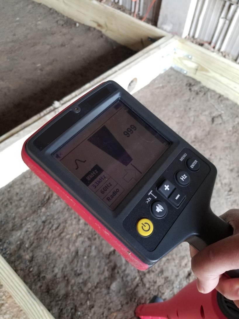
The locator indicates the presence of a buried utility by the strength of the signals returned to the receiver. The signal strength depends on the pipe’s depth, size, material type, and the presence of other confounding EM sources in the area. The operator may manually adjust the threshold for what constitutes a sufficiently strong signal against background noise for identifying a buried utility. However, some modern cable locators have automated routines for adjusting this threshold. Cable locators typically relate the location of a buried utility using a visual cue on the instrument and an audible tone that grows in intensity depending on the distance from the utility, maximizing when the operator has the instrument directly over the utility (figure 3). The operator marks this location onsite with marking paint, a flag, or some other marking tool at regular intervals to map the lateral position of the buried utility.

With ideal soil conditions, the effective locating depth of the direct method is about 10 ft (3.1 m), but this depth reduces considerably in dry sand and alkaline and high iron-content soils.(2) The method works well with aluminum, steel pipes, copper, and other metallic utilities that are buried with tracing materials above the utility itself but does not work on nonconductive utilities, such as those made of glass. However, operators can easily overcome this obstacle in many cases. For example, if a nonconductive pipe is accessible, an insulated trace wire connected to the transmitter can be traced through the pipe. The operator then waves the receiver close to where the pipe is buried and marks its horizontal location.
Pipe and cable locating instruments use a small yet crucial range of the EM spectrum, with frequencies ranging from about 50 to 480 kHz.(3) The instruments can either be single-frequency devices or multifrequency devices. The former tends to be more cost effective in terms of hardware acquisition, while the latter tends to offer a greater range of effectiveness.
Data Acquisition
Data collection with a cable locator tool should be carried out by an experienced and qualified operator. The following list comprises the general steps required to achieve quality results during a utility investigation.
Fieldwork Preparation
The following steps assume that no prior or reliable information on the utility locations is available. While historical documents and onsite landmarks can be used to make informed decisions about the approximate locations of buried utilities, these steps should be considered in a systematic approach to locating utilities, adjusting for efficiency where possible:
- Identify an area of interest for the investigation with an appropriate coordinate system laid out using semipermanent marking paint to identify its extents and major features. This coordinate system should have the following features:
- A well-defined, easily identifiable, and reasonably permanent origin from which all lateral measurements across the test area can be referenced.
- An intuitive selection of the x- and y-axis orientation for the coordinate system.
- Indications at regular intervals along each grid axis to denote the distance from the reference origin to identify the start location and orientation of a given scan.
- Document the coordinate system with a sketch from the field showing the appropriate field measurements of its extents, reference origin, x- and y-axis orientation, and a north arrow. In addition, document the weather conditions, observed soil conditions, and other relevant details for context when analyzing the gathered data.
- Complete the definition of the test area extents, even when using a cable locator in combination with Global Positioning System (GPS)-enabled survey equipment, for quality control of the data positioning. In this case, the extents are locked in using appropriate GPS equipment and relevant procedures for coordinate lock-in operations.
- Determine and document the intervals along the test area where the scans will be gathered, forming a test grid. Scans should be taken in both the x-direction and y-direction along the grid because cable locators are generally polarized, so they can only detect pipes oriented perpendicular to the instrument. A typical spacing may be 5 ft (1.5 m) in either direction, with a 2-ft (0.6 m) spacing for high-resolution imaging.
- Prepare appropriate marking tools for labeling locations where buried utilities are detected by the cable locator, ensuring they will be visible long enough for documentation and use by the site owner.
System Operation
The following steps apply to using the passive location method:
- Power on the cable locator receiver per the manufacturer’s instructions and review all system components to ensure it is properly receiving signal.
- Adjust the settings to ensure indicators, such as the visual and audible cues for a detected utility, are sufficient for observation while performing the inspection.
- Tune any threshold settings for when the instrument should provide an alert, ensuring the instrument is over an area where a utility line is not suspected to be located, to appropriately set the threshold above the local noise floor.
The following steps apply to using the active location method:
- Follow the manufacturer’s instructions for setting up the transmission system to induce current in a given buried utility.
- Power on the cable locator receiver per the manufacturer’s instructions and review all system components to ensure it is properly receiving signal.
- Adjust the settings to ensure indicators, such as the visual and audible cues for a detected utility, are sufficient for observation while performing the inspection.
- Tune any threshold settings for when the instrument should provide an alert, ensuring the instrument is over an area where a utility line is not suspected to be located, to appropriately set the threshold above the local noise floor.
- Set the cable locator to the appropriate frequency range for detecting the transmitted signal in a buried utility line.
Field Data Collection
- Operate the instrument according to the manufacturer’s instructions on system operation, beginning with the cable locator aligned on the appropriate start location on the coordinate system. Complete the scan collection systematically along the test grid in both directions, with notes and documentation gathered where appropriate.
- Sweep the cable locator tool side to side above the ground, remaining alert for any indication of a possible buried utility.
- When the locator detects a possible buried utility, sweep the locator around the general area to maximize the indication signal strength before the location is marked.
- Continue to sweep the instrument around the marked location after the utility has been located to identify the orientation of the pipe with an additional point, following the same process of maximizing the signal before marking.
- Trace the utility line in this way for its full length within the area of interest and mark at regular intervals with lines and arrows that indicate orientation and are visible from a distance.
- Document the utility line’s position appropriately in the notes once it is sufficiently marked and mapped.
- Locate other utility lines, if needed, by returning to the original place on the survey grid and continuing to scan, using the same process described in this list, when other possible utilities are encountered.
Data Processing
Most cable and pipe locator tools do not produce data files or results for later processing. While this lack of raw data can mean a lack of repeatability and reliance on the subjective choices of the operator, the general value of cable and pipe locators lies in their speed and ease of operation for performing successful utility location with direct feedback onsite.
Data Interpretation
Cable and pipe locator tools generally do not produce any data files or results for later interpretation. Typical applications of these instruments tend to focus on the marking and mapping of utilities onsite for immediate use by site owners and operators, though drawings of the mappings may be generated from notes and sketches gathered in the field.
Advantages
- Well-established field data collection process.
- Advanced training not required for operation.
- Instantaneous feedback and results for taking action.
- Reliable and repeatable method, especially for utilities made of metal.
Limitations
- Settings and thresholds can introduce subjectivity into the detection process if an operator finds the default settings and thresholds to be ineffective.
- Data are negatively influenced by the presence of significant moisture content or clay in the area under investigation.
- The locator cannot detect fiber optic utilities that lack a metallic tracer cable.
References
- Reiter, D., V. Napoli, J. Cohen, S. Boone, P. Moseley, A. Alhasan, and J. Salerno. 2023. Availability, Feasibility, and Reliability of Available Nondestructive Evaluation (NDE) Technologies for Detecting and Locating Buried Utilities. Washington DC: Federal Highway Administration.
- American Society of Civil Engineers. 2002. Standard Guidelines for the Collection and Depiction of Existing Subsurface Utility Data. New York, NY: American Society of Civil Engineers.
- Jeong, H. S., and D. M. Abraham. 2004. “A Decision Tool for the Selection of Imaging Technologies to Detect Underground Infrastructure.” Tunnelling and Underground Space Technology 19, no. 2: 175–191.


