Bridge - Acoustic Emission (AE)
Target of Investigation
AE technology is typically applied to steel bridges to monitor existing cracks or detect the development of cracks at a particular location on the structure. AE technology can also be applied to monitor a retrofit that is intended to arrest cracks or stop new fatigue cracks from developing. AE technology can be applied to detect and monitor cracks in the following elements:
- Steel girders.
- Truss members.
- Pin and hanger assemblies.
- Eyebars.
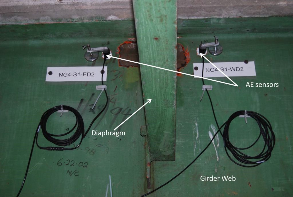
Figure 1 shows AE sensors mounted on a steel girder to detect the development of cracks in the weld between the web and diaphragm.

AE signals released from cracks developing in the weld and are detected by the sensors. Sensors are connected to a data acquisition system that detects AE events and identifies events resulting from crack initiation.
Description
AE technology uses NDE techniques for detecting, locating, and monitoring fatigue cracks in steel bridges. AE can be used on a wide variety of metal structures, including airframes, pipelines, and pressure vessels. AE is implemented by mounting one or more acoustic sensors on the surface of the material being tested to detect transient elastic waves produced by the evolution of damage in the material; for example, when a crack increases in length due to the application of load, acoustic waves are produced. These waves spread through the material and are detected by the acoustic sensors mounted on the surface. The waveform signals detected by the acoustic sensor(s) are analyzed to determine the rate at which AE signals produced from damage evolution are occurring. This analysis helps locate the damage and estimate the rate at which the damage is progressing.
AE signals are produced by the progression of damage such as the increase in length of a fatigue crack; therefore, loading must be applied to cause the damage to progress. For crack detection in highway bridges, a structure is monitored over time as traffic loads are applied to the bridge, which may result in crack growth. If a fatigue crack is not increasing in length, AE signals generally are not produced. Consequently, AE is not an effective method for detecting arrested cracks or other damage not progressing under load application.
The position of the AE source can be found by triangulating based on the arrival time of the acoustic waves and the wave velocity in the material. Additional sensors may be employed as “guard” sensors to detect AE signals generated from sources outside an area of interest.
AE technology is commonly used to monitor crack growth in steel bridges or determine if a retrofit intended to arrest cracking has been successful. AE can also be used to detect a crack that is progressing; for example, AE may be used to monitor a structural detail that is susceptible to crack growth to detect the development of a new crack.
Physical Principle
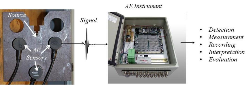
AE is an NDE technique that is used to detect damage in materials by analyzing acoustic signals produced from cracks and other defects. AE is defined as the rapid release of energy in the form of a transient elastic stress wave generated by an acoustic source. Crack growth, crack fretting, and corrosion act as acoustic sources during damage evolution, producing transient elastic waves (i.e., acoustic waves). The acoustic waves can be detected by placing sensors on the surface of the material. Figure 2 illustrates the principles of AE schematically. A stimulus, such as an applied load, results in increasing damage in the material such as the extension of a crack. When the crack extension occurs, one or more bursts of waves are released and propagate through the material. A sensor placed on the surface of the material detects the acoustic wave and records the waveform signal for analysis. The waveform signals are analyzed to detect the progression of damage in the material.(1,2,3)

Data Acquisition
Equipment for conducting AE monitoring consists of acoustic sensors, data acquisition electronics, and a computer to analyze the data. Signals received from each sensor are digitized and analyzed with a computer system using specialized software.
Acoustic sensors are ultrasonic sensors in the 50 kHz to 1 MHz frequency range with integrated preamplifiers. The integrated preamplifiers are required to detect the AE waveforms produced from damage in the material because the acoustic signals are very low in amplitude.

Data Processing
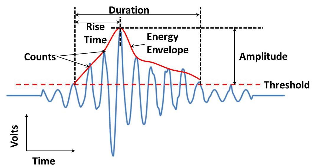
Recorded waveforms are analyzed to determine if the source of the waveform is damage or simply ambient noise caused by non-relevant noise sources, such as friction between surfaces, the movement of bolted connection or bearings, etc. Parameters of the waveform are determined as a means of discriminating noise from relevant AE signals. For example, figure 3 shows a typical AE waveform. Parameters that describe this waveform include the amplitude of the wave, the rise time, the total energy in the wave packet, and the number and duration of “counts” or wave cycles recorded that exceeded a certain threshold. Other parameters, such as the frequency characteristics of the waveform and geometric shape of the wave packets, may also be used. These parameters are then used to discriminate between acoustic waves corresponding to damage evolution and ambient noise. Waveforms that correspond to damage evolution are called “AE events.”(2)
Data Interpretation
The rate of occurrence of AE events is interpreted to identify AE sources in the material, i.e. damage. The location of the source of the AE signal is also used in the interpretation of results. For example, a high number of AE events emanating from a particular location in a structure during the application of loads may be interpreted to indicate damage at that location. The rate of AE events generally increases when damage increases. The increase in AE activity is interpreted as an indication that the damage is increasing. For example, as a crack grows as a result of applied loads, the number of AE events increases. The rate of increase in length can be estimated from the rate of increase in AE activity.
Advantages
- Can be used to monitor large areas of a structure.
- Can detect crack growth and estimate crack growth rates.
- Can be used to monitor complex geometries where other NDE technology may be ineffective.
- Can be used to monitor for damage located in inaccessible areas.
Limitations
- Complex data interpretation. Acoustic signals can result from many sources in addition to a crack or defect.
- Can only detect increasing damage (for example, a crack that is growing).
References
- American Society of Nondestructive Testing (ASNT) Handbook, 3rd Edition, Vol.6, pp. 32, 2005.
- Gostautas, R., Steel Bridge Testing Program (Interim report) “Evaluation of an Acoustic Emission Inspection System” submitted by Physical Acoustics Corporation to FHWA NDE, December, 2008.
- Huang, M., Jiang, L., Liaw, K.P., Brooks, R.C., Seeley, R. and Klarstrom, L.D., “Using Acoustic Emission in Fatigue and Fracture Materials Research,” The Minerals, Metals & Materials Society, 1998.


